Document Edition 3.1 Page 1 of 35
APPLICATION GUIDE
Delta Network Sensor Thermostat: BACstat II
DNS-24, DNT-T103, & DNT-T221
Document Edition 3.1
Product Description
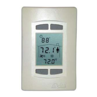
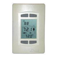
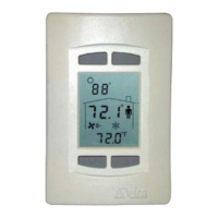
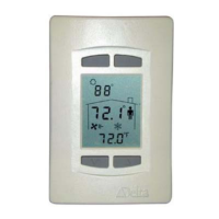
The BACstat II is an intelligent 4-button room sensor/thermostat with a
custom 3-value, 96 segment LCD display that is used with Delta’s product
line of BACnet Application Controllers. It is capable of displaying a wide
range of digital or analog values, and is capable of communicating on Delta’s
proprietary LINKnet network or directly on a BACnet MS/TP network.
When connected to an Application Controller on a LINKnet network it
provides programmable remote sensor and expanded I/O capabilities to the
controller. When connected on an MS/TP network it functions as an
independent BACnet sensor device or a small local controller.
The DNS-24 model does not have additional I/O and built-in control strategies, while the DNT-T103 has 1
extra input, 3 binary outputs and a number of built-in application control strategies. The DNT-T221 has 2
extra inputs, 2 analog and 1 binary outputs and built-in application control strategies. As a result, the DNT-
T103 and DNT-T221 BACstats are capable of simple stand-alone control when directly connected on an
MS/TP network. When connected to a LINKnet network, the additional I/O may be MUXed or otherwise
controlled from the Application Controller it is connected to.
Contents
OTHER
RELEVANT DOCUMENTS................................................................................. 2
IMPORTANT
INFORMATION.......................................................................................... 2
SETUP
& CONFIGURATION ............................................................................................ 3
N
ETWORK COMMUNICATIONS .......................................................................................... 3
D
EVICE CONFIGURATION (KEYPAD) ................................................................................. 3
S
ERVICE TOOL MODE (KEYPAD) ...................................................................................... 6
I
NPUT CALIBRATION ......................................................................................................... 8
I
NPUT SCALE RANGES....................................................................................................... 8
SOFTWARE
& PROGRAMMING..................................................................................... 9
O
BJECTS............................................................................................................................ 9
P
ROGRAMMING ............................................................................................................... 10
CONTROL
FUNCTIONS................................................................................................... 12
OVERVIEW ...................................................................................................................... 12
S
OFTWARE LOOP CONTROLLER ...................................................................................... 13
S
ETPOINTS ...................................................................................................................... 16
C
ONTROL DIAGRAM........................................................................................................ 17
C
ONTROL APPLICATIONS (MUX, VAV, VVT, HPU, FCU, RAD, HUM) .......................... 18
O
UTPUT FUNCTIONS & TYPES......................................................................................... 26
OWS
FUNCTIONS ............................................................................................................. 30
APPENDIX (LCD Object Property Values & Programming Notes).............................. 32