Delta Controls
Document Edition 3.1
Page 9 of 35
Software & Programming
OBJECTS
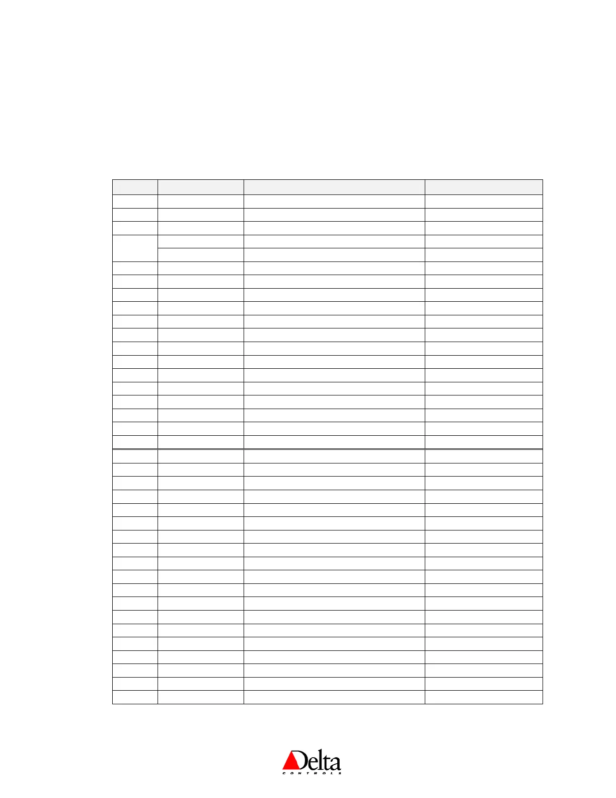
The following is a list of predefined or “fixed” objects that reside in the BACstat II products, which you
cannot create or delete. When connected to an MS/TP network, these objects are readily accessible over
the network. When connected to a LINKnet network, many of these objects are mapped into matching AI
or AV objects residing in the Application Controller above.
Object Name Description Default Value
DEV1
BACstat * Device Object N/A
AI1
Temperature Input 1 (10K Thermistor Value) N/A
AI2 Input 2 * Input 2 (Available Input) N/A
AI3
Humidity Input 3 (Humidity on DNT-T103) N/A
Input 3 Input 3 (Extra Input on DNT-T221) N/A
AV1 Output 1 * Output 1 (0 – 100%, Name Changes) N/A
AV2 Output 2 * Output 2 (0 – 100%, Name Changes) N/A
AV3 Output 3 * Output 3 (0 – 100%, Name Changes) N/A
AV4
KeyPress KeyPress Value N/A
AV5
External * External Object Value (i.e., OAT) N/A
AV6
Day Setpoint Room Setpoint ºC = 21; ºF = 71; % = 30
AV7
Day Minimum Minimum Adjustable Day Setpoint ºC = 18; ºF = 65; % = 20
AV8
Day Maximum Maximum Adjustable Day Setpoint ºC = 25; ºF = 77; % = 55
AV9 Day Differential Room Setpoint Differential ºC = ±0.5; ºF = ±1, % = ±2.5
AV10
Night Heat Setpoint Night Setpoint for Heating (or Humidity) ºC = 16; ºF = 60; % = 30
AV11
Night Cool Setpoint Night Setpoint for Cooling ºC = 30; ºF = 86; % = 30
AV12 Application Control Application (Name Changes) None
AV13
Alg Mode Algorithm Mode 0 (O
FF or Night)
AV14 Controller Status Status of Internal Control Loop N/A
AV15
Display Code Local Display & Button Handling As per Control Application
AV16
AI1 Calibration Input 1 Calibration (Temperature) 0.0
AV17 AI2 Calibration Input 2 Calibration (MUXed IP) 0.0
AV18
AI3 Calibration Input 3 Calibration (Humidity) 0.0
AV19 Proportional Band Control Loop Tuning Parameter ºC = 1; ºF = 2; % = 10
AV20 Reset Rate Control Loop Tuning Parameter 1.0
AV21 Output 1 Config Output 1 Configuration Variable As per Application Setup
AV22 Output 2 Config Output 2 Configuration Variable As per Application Setup
AV23 Output 3 Config Output 3 Configuration Variable As per Application Setup
AV24 Setup 1 Setup Variable 1 (Name Changes) As required
AV25 Setup 2 Setup Variable 2 (Name Changes) As required
AV26 Setup 3 Setup Variable 3 (Name Changes) As required
AV27 Setup 4 Setup Variable 4 (Name Changes) As required
AV28 Setup 5 Setup Variable 5 (Name Changes) As required
AV29 Setup 6 Setup Variable 6 (Name Changes) As required
AV30
Baud Rate Network Baud Rate 76,800 bps
AV31
PIN PIN (4-Bit Configuration Access Code) 1011
AV32
Service Tool Mode Service Tool Access Disable/Enable (0-2) 1 (or 2 when AV12 = VAV)
AV33 Box Mode Heating & Cooling Modes for VAV/VVT 0 (Cooling)
* Names are user settable (to a maximum of 8 characters), and only on outputs when they are controlled remotely (i.e., MUXed).
These are the typical objects that may be commanded on-the-fly by a user or from GCL, and would also include the Outputs
(AV1-3) when they are MUXed. Never command the Configuration Variables (AV12, AV21-13) on-the-fly. Refer to page 34.
 Loading...