Do you have a question about the Delta Electronics CTA4 and is the answer not in the manual?
Can be a timer, counter, or tachometer and can operate in timer + counter mixed mode.
There are currently two model types available: CTA4000A and CTA4100A, only differentiating in the type of output 2.
Lists technical specifications like power input, display, and environmental ratings.
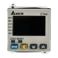
Explains the function of various indicators and keys on the device.
Provides detailed physical dimensions of the CTA unit.
Defines the purpose of different terminals based on operating modes.
Outlines the preset parameters for timer, counter, tachometer, and mixed modes.
Details the DIP switch configurations for timer and counter modes.
Explains the timer function, including counting up/down modes.
Describes how to set the time units for the timer function.
Guides on configuring timer parameters like mode, output, and signal settings.
Details the different counter functions: 1-stage, 2-stage, batch, total, dual.
Explains how to configure counter parameters like mode, speed, and signal types.
Explains how the tachometer measures pulse width and displays frequency.
Guides on configuring tachometer settings like output modes, speed, and averaging.
Describes the mixed mode where timer controls OUT1 and counter controls OUT2.
Explains how to configure parameters for the mixed timer and counter mode.
Details using the counter function for cut-to-length applications with an encoder.
| Output Frequency | 50/60 Hz |
|---|---|
| Enclosure Rating | IP20 |
| Input Voltage | 100 ~ 240 VAC |
| Protection Functions | Overvoltage, Overcurrent |
| Communication | RS-485, Modbus RTU |
| Resolution | 0.1V |
| Power Supply | 100 ~ 240 VAC |
| Relative Humidity | 5% to 95% non-condensing |
| Storage Temperature | -20°C to +70°C |