INSTALLATION SM6000
Page 4 - 1 DELTA ELEKTRONIKA B.V. rev. June 2018
4 INSTALLATION
1) HU MID ITY & CON DEN SA TION
• Dur ing nor mal op er a tion, hu mid ity will not harm the power sup ply,
pro vided the air is not ag gres sive. The heat nor mally pro duced in
the power sup ply will keep it dry.
• Avoid con den sa tion in side the power sup ply, to pre vent
break-down. Con den sa tion can oc cur dur ing a pe riod the power
sup ply has been switched off (or op er at ing at no load) and the am -
bi ent tem per a ture is in creas ing. Al ways al low the power sup ply to
dry be fore switch ing it on again.
2) TEM PER A TURE & COOL ING
• The stor age tem per a ture range is –40 to +85 °C.
• The op er at ing tem per a ture range at full load is –20 to +50 °C.
This tem per a ture range only holds when the air-in takes and
air-out lets are un ob structed and the tem per a ture of the air-in take
is not higher than +50 °C.
• When the power sup ply is mounted in a cab i net, please note that
the tem per a ture of the air-in take should be kept low and avoid a
short cir cuit in the air flow i.e. the hot air leav ing the air-out lets
en ter ing the air-in takes again.
• Please note: a lower tem per a ture ex tends the life time of the
power sup ply.
3) 19" RACK MOUNT ING
• On both sides in the rack, mount a proper sup port slide that can
hold the weight of the unit. It is ad vised to use a sep a rate slide for
each unit.
• Af ter plac ing the unit on the slide, add all 4 screws to mount the
front panel of the power sup ply to the ver ti cal rack posts. Use
proper screws in tended for keep ing equip ment of this weight in
po si tion.
• As sum ing the rack is de lib er ately de signed for the weight, stack -
ing of the units is al lowed with out lim i ta tions. See pre vi ous para -
graph for cool ing in struc tions.
4) OP ER ATING THE UNIT FOR THE FIRST TIME
• Check there is no con den sa tion on the unit. If there is, al low some
time to dry.
• Check there is a link be tween + and S+ and be tween – and S– on
the SENSE BLOCK (on rear panel).
• Check there is a link be tween the in puts of the In ter lock (CON A).
• Set the CV and CC po ten ti om eters to min i mum (fully anti clock -
wise). For units with Op tion P220, this is not needed. These units
are set to start at 0 V - 0 A when op er ated for the first time.
• For the in put power, con nect a ca ble of 4-wires of 2.5mm
2
. Use a
torque of 0.6Nm to fas ten the screws on the in put con nec tor.
• For the out put power, see ta ble 4 - 1 for ca ble di am e ters and
mount ing torque .
• With high out put cur rent make sure to use low re sis tive con nec -
tions be tween the power sup ply and the load:
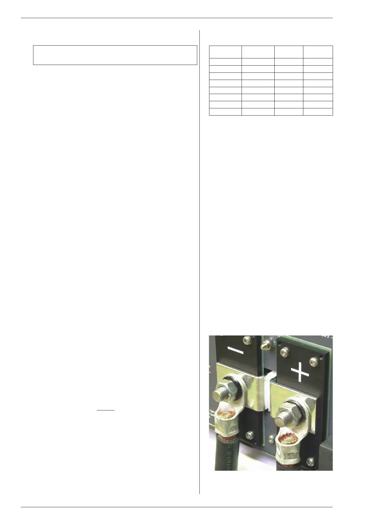
- Mount the ca ble lugs di rectly
on the tinned out put strips
fol lowed by a washer, a split washer and a nut (see fig. 4 - 1).
Al ways in this or der!
- Never place wash ers be tween the lugs and the strips
be cause this can re sult in ex ces sive heat!
- Only use nuts and wash ers sup plied with the unit.
• Switch on unit.
• Dis able the Key lock func tion, see next para graph 5) .
• Check the unit is not in Re mote CV or Re mote CC (LED’s for this
func tion should be off). Press the RE MOTE/LO CAL but ton un til
both LED’s are off.
• Turn on the out put by press ing the OUT PUT ON/OFF but ton.
• Turn both the CV and CC po ten ti om e ter a few turns clockwise.
A volt age should now be pres ent on the out put.
fig. 4 - 1
Low re sis tive ca ble con nec tion by mount ing the
ca bles di rectly on the tinned out put strips.
Unit Ca bles
[mm2]
Bolts Torque
[Nm]
SM15-400 150 M12 80
SM30-200 70 M10 40
SM45-140 35 M10 40
SM60-100 35 M10 40
SM70-90 25 M10 40
SM120-50 10 M8 20
SM300-20 4 M8 20
SM600-10 2.5 M8 20
ta ble 4 - 1
Ca ble di am e ters and torque.
Warn ing: care fully read the chap ter "Safety In struc tions"
in this man ual be fore op er at ing the unit!
 Loading...