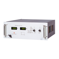
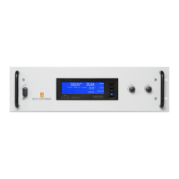
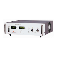
Do you have a question about the Delta Elektronika SM 18-50 and is the answer not in the manual?
Evaluated to installation category II. (Over voltage category II)
Ensure proper grounding to minimize shock hazard. Safety Class 1 instrument.
Fuses must be changed by authorized personnel only for fire protection.
Do not exceed specified input voltage and frequency ratings.
Never remove covers or replace components with power connected.
Only authorized personnel for parts substitutions/modifications.
Proper disposal of electronic waste in the European Union. Recycle responsibly.
Constant voltage/current source with voltage/current limiting.
Power supplies have a wide input voltage range.
Unit has active power factor correction (PFC).
Consumes very little power in standby mode.
Very high and constant efficiency over wide output current range.
CV-load regulation measured directly on output terminals.
For accurate CC-load, do not use external voltage sensing.
Very low output ripple with almost no spikes. Measure directly on terminals.
Program voltage/current via external analog voltage. Standardized on 5V.
Prevent earth loops for accurate programming. Use optional ISO AMP CARD.
Ethernet, IEEE 488, RS232 programming via controllers.
Voltage 0-5V proportional to output current/voltage. Buffered with op-amps.
Used to supply external circuits. Current limited.
Logic outputs indicating status like limit settings. Can drive opto-couplers or TTL gates.
Two status relay outputs with change-over contacts for DCF/ACF faults.
-20 to +50°C at full power. Derate above 50°C.
Shuts down output if cooling is insufficient. OT status high.
Depends on load and output voltage. Lighter load = longer hold-up.
Output voltage available approx. 0.5s after mains switch on.
Limited by a special circuit. Avoid fast switching.
Keeps load voltage constant by compensating for voltage drop in leads.
Allowed up to 600V total voltage without special precautions.
Units can be connected in parallel without special precautions.
Form one large unit using multiple supplies. Manual or programmed on master.
Maintain safe preset output value. Set via display buttons and screwdriver.
Details on CV, CC, Voltage Limit, Current Limit controls.
Low noise blower cools the unit. Fan speed depends on heatsink temperature.
Provides overall dimensions of the unit for installation planning.
Voltage or switch contact can shut down the output. RSD LED indicates status.
Shuts down output if interlock connection is disrupted.
Affects rise and fall times for voltage/current programming.
AC component of load current must be limited to avoid overheating.
Input/output separation tested at 3750 Vrms.
Initial unit setup: check connections, set potentiometers, switch on.
Prevents accidental output shutdown via front panel buttons.
Use CON E for programming via voltage source (0-5V).
For isolated analog programming via CON H.
Ethernet, IEEE 488, RS232 programming via PSC controllers.
5V levels compatible with most interfaces, drive meters directly.
Outputs indicate status; protected by self-resetting fuse.
Keeps load voltage constant by compensating for voltage drop in leads.
Ideal for charging batteries constantly without overcharging.
Control output via voltage or relay contact on CON E.
Connect units in series for higher total voltage, controlled by master.
Connect units in parallel for higher total current, controlled by master.
Master/Slave not recommended; test combinations with load.
Use M/S adapter for complex combinations.
Defines temperature ranges for operation and storage.
Avoid condensation; allow unit to dry if condensation occurs.
Take precautions against aggressive environments.
No routine maintenance or calibration needed. Ensure cooling is unobstructed.
Inspect fan and heatsink regularly. Thermal protection prevents damage.
Contact engineers for repair assistance; use RMA form.
Check LEDs, Keylock, SENSE BLOCK links, and potentiometers.
Check Remote mode, fuses, and programming source grounding.
Caused by earth loops; use floating source or ISO AMP CARD.
Check fuse F27_2 for issues with status outputs.
Check wiring voltage drop and inductance.
Check SENSE BLOCK connections and remote sensing wires.
Indicates internal heatsink temperature is too high. Check fan and airflow.
Pre-warning for high heatsink temperature. Check fan and airflow.
Indicates low or intermittent input voltage. Check connections.
Indicates output voltage below set point or Interlock interruption.
Indicates Power Sink overload or high temperature.
Check input. Send unit for repair if no LEDs are on.
Blinking LEDs indicate Keylock function is activated.
Factory calibrated; calibration needed only after special repairs.
Calibrate full scale indication using potentiometers on P673.
For current monitor offset and max current range. Requires qualified personnel.
| Output Voltage | 0-18 V |
|---|---|
| Output Current | 0-50 A |
| Power Rating | 900 W |
| Efficiency | Up to 88% |
| Weight | 4.5 kg |
| Input Voltage | 90-265 VAC |
| Frequency | 47-63 Hz |
| Voltage Regulation | 5 mV |
| Current Regulation | ≤ 0.1 % |
| Operating Temperature | 0 to +50°C |
| Humidity | 0 to 80 % |
| Protections | Overvoltage, Overtemperature |
| Cooling | Fan cooled |


 Loading...