Do you have a question about the Delta Tau Geo Brick and is the answer not in the manual?
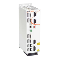
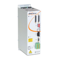
Overview of the Geo Brick Drive product.
Categorization of the Geo Brick Drive.
References for further information on Turbo PMAC software.
Information on using Turbo PMAC script examples.
Details on the part numbering scheme for Geo Brick Drives.
Overview of available CPU and encoder feedback options.
Operational temperature, humidity, and altitude limits.
Electrical protection limits including over-voltage and over-current.
Certifications obtained by the Geo Brick Drive.
Detailed electrical characteristics for different axis configurations.
Guidelines for proper and safe utilization of the Geo Brick Drive.
Identification of connectors on the front, top, and bottom views.
Wiring and pinout details for the main power input connector.
Procedure for safely powering the drive on and off.
Guidelines for repeatedly cycling the main bus power.
Best practices for wiring and protecting the main bus power.
Connection and use of logic power and STO safety feature.
Procedure to disable STO for backward compatibility.
Instructions for wiring and utilizing the STO safety function.
Details on connecting an external shunt resistor for deceleration.
Pinout and configuration for axis 1-4 limit and flag inputs/outputs.
Pinout and configuration for axis 5-8 limit and flag inputs/outputs.
Wiring methods for limits and flags (sinking or sourcing).
Recommended M-variables for axis 1-4 limit and flag configuration.
Recommended M-variables for axis 5-8 limit and flag configuration.
Pinout and configuration for general purpose digital I/Os.
Pinout and configuration for additional digital I/Os.
General information on digital I/O operation and wiring.
Details on connecting to third-party PWM amplifiers.
Pinout and configuration for handwheel and analog I/O.
Configuration steps for analog inputs using Option 12.
Configuration steps for analog outputs (filtered PWM).
Configuration for pulse and direction output signals.
Configuration for using the handwheel port.
Pinout and setup for quadrature encoder feedback.
Procedure for configuring quadrature encoders.
Explanation and handling of encoder count errors.
Detection and handling of quadrature encoder signal loss.
PFM output configuration for external stepper amplifiers.
Pinout and setup for sinusoidal encoder feedback.
Procedure for configuring sinusoidal encoders via ECT.
Explanation and handling of encoder count errors.
Detection and handling of sinusoidal encoder signal loss.
Pinout and setup for resolver feedback devices.
Setting the excitation magnitude for resolver channels.
Setting the excitation frequency for resolver channels.
Using the ECT utility for resolver feedback processing.
Method for calculating tracking filter gains.
Pinout and setup for HiperFace encoder feedback.
Configuration for HiperFace on-going position using ECT.
Configuration for absolute position read with HiperFace.
Programming serial encoder interface clock and trigger.
Defining channel-specific serial encoder parameters.
Memory locations for HiperFace absolute power-on data.
Example configuration for HiperFace encoders.
PLC example for initializing global and channel control registers.
HiperFace encoder data stream format for channels 1-4.
Internal definitions and substitutions for configuration.
Explanation and handling of encoder count errors.
Detection and handling of HiperFace encoder signal loss.
Pinout and setup for SSI encoder feedback.
Programming serial encoder interface clock and trigger.
Defining channel-specific serial encoder parameters.
Memory locations for SSI encoder data.
Example configuration for SSI encoder registers.
PLC example for power-on register configuration.
Pinout and setup for EnDat encoder feedback.
Programming serial encoder interface clock and trigger.
Defining channel-specific serial encoder parameters.
Memory locations for EnDat encoder data.
Example configuration for EnDat encoder registers.
Pinout and setup for BiSS C/B encoder feedback.
Programming serial encoder interface clock and trigger.
Defining channel-specific serial encoder parameters.
Memory locations for BiSS encoder data.
Example configuration for BiSS encoder registers.
Methods for setting up SSI, EnDat, and BiSS encoder protocols.
Summary of recommended setup techniques for absolute encoders.
Selecting commutation source and type for brushless motors.
Explanation of the resolution scale factor parameter.
Setting the commutation cycle size parameters.
Tuning position and velocity scale factors and error limits.
Example configuration for Technique 1 setup.
Calculating counts per revolution for Technique 1.
Setting up absolute position read using Technique 1.
Example configuration for Technique 2 setup.
Calculating counts per user units for Technique 2.
ECT setup for commutation using Technique 2.
Setting up absolute position read using Technique 2.
Example configuration for Technique 3 setup.
Calculating counts per user units for Technique 3.
ECT setup for commutation using Technique 3.
Setting up absolute position read using Technique 3.
Pinout and setup for Yaskawa Sigma II/III encoder feedback.
Data registers for Yaskawa encoder feedback.
Programming serial encoder interface clock and trigger.
Defining channel-specific serial encoder parameters.
ECT setup for Yaskawa Sigma II encoders.
Setting position and velocity pointers for Yaskawa encoders.
Setting up absolute position read for 16-bit Yaskawa encoders.
Details on the Yaskawa Sigma II 17-bit absolute encoder.
ECT setup for Yaskawa Sigma II 17-bit encoders.
Setting up absolute position read for 17-bit Yaskawa encoders.
Details on the Yaskawa Sigma III 20-bit absolute encoder.
ECT setup for Yaskawa Sigma III 20-bit encoders.
Setting up absolute position read for 20-bit Yaskawa encoders.
Details on the Yaskawa Sigma II 13-bit incremental encoder.
ECT setup for Yaskawa Sigma II 13-bit encoders.
Details on the Yaskawa Sigma II 17-bit incremental encoder.
ECT setup for Yaskawa Sigma II 17-bit incremental encoders.
List of alarm codes for Yaskawa incremental encoders.
Procedure for homing with Yaskawa incremental encoders.
Pinout and configuration for X9-X10 analog I/O.
Pinout and configuration for X11-X12 analog I/O.
Configuration steps for analog inputs.
Recommended M-variables for analog input configuration.
Configuration steps for analog outputs.
Recommended M-variables for analog output configuration.
Configuration for general purpose relay and brake output.
Wiring diagram for high true brake output (sourcing/sinking).
Wiring diagram for low true brake output (sourcing/sinking).
Configuration for external amplifier fault input.
Details on establishing USB communication.
Details on establishing Ethernet communication.
Configuration of watchdog timer and ABORT input.
Wiring instructions for the Abort input.
Wiring instructions for the Watchdog output.
Details on the RS-232 serial communication port.
Wiring instructions for connecting motors to axes A1-A8.
Guidelines for proper motor cabling and noise reduction.
Step-by-step instructions for setting up motors.
Overview of the motor setup process.
Selection criteria for clock settings based on application requirements.
Default clock settings suitable for most applications.
Explanation of hardware clock settings for enhanced performance.
Setting the ADC Strobe Word for default and enhanced modes.
Setup instructions for AC/DC brushless motors.
Setting commutation angle and current mask parameters.
Calculating and setting the PWM scale factor.
Setting commutation position and enable parameters.
Configuring I2T protection for continuous/instantaneous currents.
Setting commutation cycle size based on encoder and motor parameters.
Procedure for setting ADC offsets to minimize measurement errors.
Procedure for tuning the current loop.
Discussion of various motor phasing methods.
Procedure for manual and custom motor phasing.
Phasing method for motors with relatively small loads.
Finer phasing method suitable for significant loads and torque.
Rough phasing using digital hall sensors for quadrature encoders.
Procedure for correcting hall sensor errors for optimal operation.
Rough phasing using hall sensors for Yaskawa incremental encoders.
Establishing phase reference without motor movement using HiperFace data.
Absolute phasing methods for EnDat, SSI, and BiSS encoders.
Experimental procedure to find the motor phase offset.
Configuring the power-on phase position format.
Finding absolute phase position offset for Yaskawa absolute encoders.
Procedure to verify encoder direction sense with open-loop test.
Troubleshooting steps for unsuccessful open loop tests.
PID loop tuning for position control.
Implementation of commutation delay compensation for high speeds.
Setup instructions for AC induction motors with encoders.
Setting commutation angle and current mask parameters.
Calculating and setting the PWM scale factor.
Setting commutation position and enable parameters.
Estimating and setting magnetization current and slip gain.
Configuring I2T protection for continuous/instantaneous currents.
Setting commutation cycle size based on encoder and motor parameters.
Procedure for setting ADC offsets to minimize measurement errors.
Tuning current loop gains and verifying encoder decode.
PID loop tuning for position control.
Procedures for optimizing magnetization current and slip gain.
Steps to optimize magnetization current.
Calculating and adjusting motor slip gain.
Adjusting I2T settings based on optimized parameters.
Comparison of closed-loop and open-loop motor operation modes.
Method to achieve higher speeds by reducing magnetization current.
Implementation of commutation delay compensation for high speeds.
Setup for AC induction motors without encoders using micro-stepping.
Setting commutation angle, current mask, and flag mode.
Calculating and setting the PWM scale factor.
Setting the maximum achievable motor speed and command limit.
Configuring I2T protection for continuous/instantaneous currents.
Calculating and adjusting motor slip gain.
Procedure for tuning the current loop.
Instructions for moving the motor in micro-stepping mode.
Setup instructions for DC brush motors.
Clearing phasing error bit and managing integrator output.
Calculating and setting the PWM scale factor.
Configuring I2T protection for continuous/instantaneous currents.
Procedure for setting ADC offsets to minimize measurement errors.
Tuning current loop gains and verifying encoder decode.
PID loop tuning for position control.
Introduction to the MACRO ring for distributed motion control.
Overview of MACRO interface, benefits, and formation.
Description of common MACRO ring configurations.
Explanation of MACRO IC nodes and addressing.
Syntax and examples of MACRO auxiliary commands.
Example of configuring a MACRO ring between two Bricks.
Procedure to configure a slave unit in Torque Mode.
Procedure to configure the master unit in Torque Mode.
Procedure to configure a slave unit in PWM Mode.
Procedure to configure the master unit in PWM Mode.
Activating MACRO motors and controlling flags.
Default settings for MACRO motor configuration.
I2T protection settings for a MACRO motor.
Procedure for motor phasing and open-loop testing in MACRO.
Example of configuring a MACRO ring with Geo MACRO Drives as slaves.
Activating MACRO motors based on Servo IC configuration.
Setting position and velocity pointers for MACRO motors.
Default settings for MACRO motor configuration.
Procedure for tuning the current loop for MACRO motors.
Procedure for motor phasing and open-loop testing in MACRO.
Handling I/O data transfer between Brick units in a MACRO ring.
Method for transferring digital I/O data over MACRO.
Example PLC for transferring digital I/O data from slave to master.
Example PLC for transferring digital I/O data from master to slave.
Bitwise assignments for digital I/O transfer.
Method for transferring analog I/O data over MACRO.
Method for transferring analog input data from J9 over MACRO.
Configuration of MACRO limits, flags, and homing routines.
Explanation of MACRO motors' limits and flags.
Procedure for centralized homing from the master.
Recommended M-variables for MACRO configuration.
Procedure to ensure proper MACRO communication establishment.
Overview of drive structure and troubleshooting procedures.
Description of the Geo Brick Drive's hardware architecture.
Information on identifying serial numbers and board revisions.
Setting the ADC Strobe Word for default operation.
Accessing IGBT temperature and bus voltage information.
List and description of drive error codes.
Specific error codes related to individual motor axes.
Description of global faults affecting the entire drive system.
Procedure for reading IGBT temperature and bus voltage.
Example calculation for instantaneous motor current output.
Description of the status indicated by the drive's LEDs.
Specific error code for phase reference issues.
Conditions that cause a watchdog timer trip.
List of online commands specific to the Geo Brick Drive.
Command to report amplifier processor firmware version.
Command to report Geo Brick Drive part number.
Command to report serial electronic identification number.
Command to clear amplifier faults.
Functions of the boot switch for firmware and write-protection.
Procedure for reloading PMAC firmware.
Steps to configure network settings.
Procedure to enable the ModBus communication option.
Procedure for reloading boot and communication firmware files.
Procedure for performing a factory reset of the drive.
List of significant changes and user-related updates.
Details on the AMPVER command and its importance.
Introduction of the +5V ENC PWR connector.
Explanation of EEPROM write-protect function.
Behavior of AMPVER command during configuration errors.
Summary of modifications and improvements made in later units.
Contains schematic diagrams and samples.
Visual representation of circuit designs.
Specifications related to connector spacing.
Dimensional details for DB connectors.
Information on internal control board jumpers.
Configuration jumpers on the control board.
Jumper for enabling firmware reload via BOOT SW.
Jumper for disabling the watchdog timer.
Jumper settings for encoder index input or AENA output.
Jumper settings for encoder index input or AENA output.
Details on limitations of absolute serial encoders.
Summary of limitations for absolute serial encoders.
Maximum achievable velocity in open-loop mode.
Maximum velocity achievable in closed-loop mode.
Considerations for maximum motor travel and rollover.
| Category | DC Drives |
|---|---|
| Manufacturer | Delta Tau |
| Type | Geo Brick |
| Communication Interface | Ethernet |
| Motor Types Supported | Brushless DC, Brushed DC |
| Feedback Options | Encoder, Resolver |
| Operating Temperature Range | 0°C to 50°C |