7
53915 Rev. A
4
A.
B.
D.
E.
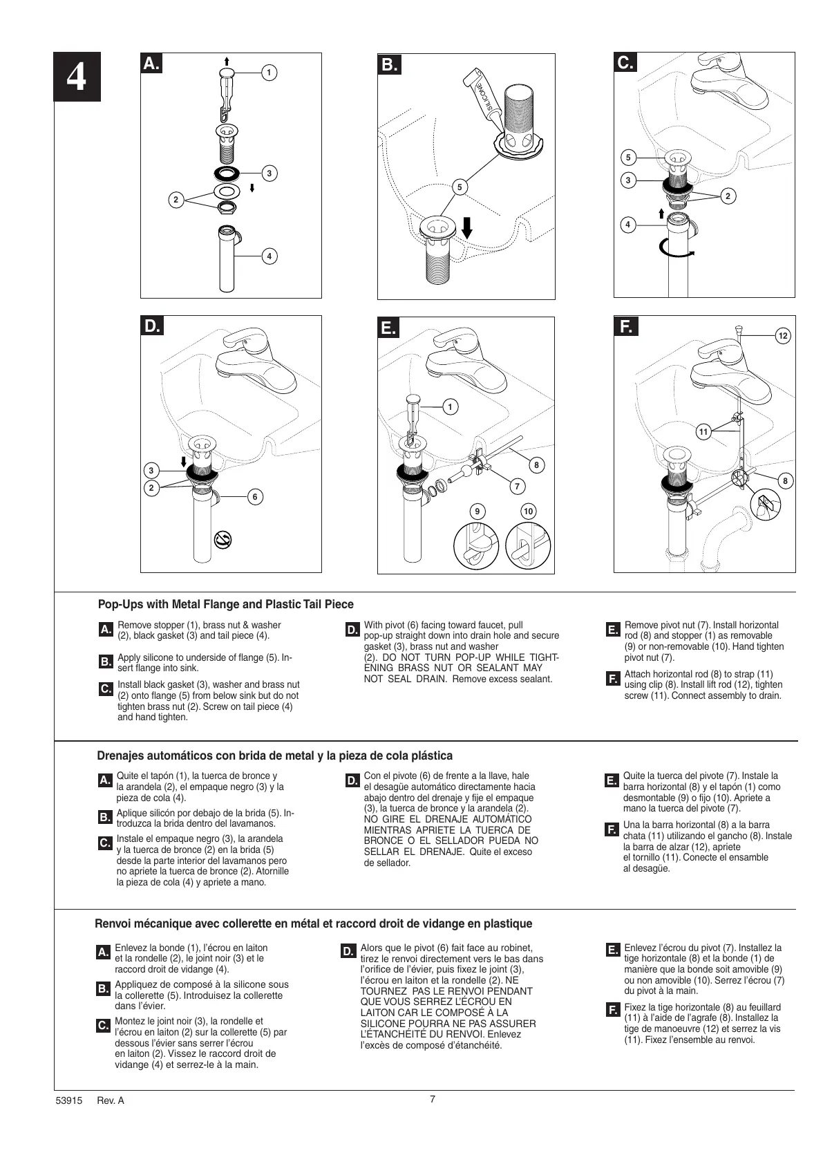
Remove stopper (1), brass nut & washer
(2), black gasket (3) and tail piece (4).
Apply silicone to underside of flange (5). In-
sert flange into sink.
Install black gasket (3), washer and brass nut
(2) onto flange (5) from below sink but do not
tighten brass nut (2). Screw on tail piece (4)
and hand tighten.
B.
A.
C.
With pivot (6) facing toward faucet, pull
pop-up straight down into drain hole and secure
gasket (3), brass nut and washer
(2). DO NOT TURN POP-UP WHILE TIGHT-
ENING BRASS NUT OR SEALANT MAY
NOT SEAL DRAIN. Remove excess sealant.
D.
Pop-Ups with Metal Flange and Plastic Tail Piece
Renvoi mécanique avec collerette en métal et raccord droit de vidange en plastique
Enlevez la bonde (1), l’écrou en laiton
et la rondelle (2), le joint noir (3) et le
raccord droit de vidange (4).
Appliquez de composé à la silicone sous
la collerette (5). Introduisez la collerette
dans l’évier.
Montez le joint noir (3), la rondelle et
l’écrou en laiton (2) sur la collerette (5) par
dessous l’évier sans serrer l’écrou
en laiton (2).
Vissez le raccord droit de
vidange (4) et serrez-le à la main.
C.
A.
B.
C.
F.
Remove pivot nut (7). Install horizontal
rod (8) and stopper (1) as removable
(9) or non-removable (10). Hand tighten
pivot nut (7).
Attach horizontal rod (8) to strap (11)
using clip (8). Install lift rod (12), tighten
screw (11). Connect assembly to drain.
F.
E.
Quite el tapón (1), la tuerca de bronce y
la arandela (2), el empaque negro (3) y la
pieza de cola (4).
Aplique silicón por debajo de la brida (5). In-
troduzca la brida dentro del lavamanos.
Instale el empaque negro (3), la arandela
y la tuerca de bronce (2) en la brida (5)
desde la parte interior del lavamanos pero
no apriete la tuerca de bronce (2). Atornille
la pieza de cola (4) y apriete a mano.
C.
A.
B.
Con el pivote (6) de frente a la llave, hale
el desagüe automático directamente hacia
abajo dentro del drenaje y fije el empaque
(3), la tuerca de bronce y la arandela (2).
NO GIRE EL DRENAJE AUTOMÁTICO
MIENTRAS APRIETE LA TUERCA DE
BRONCE O EL SELLADOR PUEDA NO
SELLAR EL DRENAJE. Quite el exceso
de sellador.
D.
Drenajes automáticos con brida de metal y la pieza de cola plástica
Quite la tuerca del pivote (7). Instale la
barra horizontal (8) y el tapón (1) como
desmontable (9) o fijo (10). Apriete a
mano la tuerca del pivote (7).
Una la barra horizontal (8) a la barra
chata (11) utilizando el gancho (8). Instale
la barra de alzar (12), apriete
el tornillo (11). Conecte el ensamble
al desagüe.
F.
E.
Alors que le pivot (6) fait face au robinet,
tirez le renvoi directement vers le bas dans
l’orifice de l’évier, puis fixez le joint (3),
l’écrou en laiton et la rondelle (2). NE
TOURNEZ PAS LE RENVOI PENDANT
QUE VOUS SERREZ L’ÉCROU EN
LAITON CAR LE COMPOSÉ À LA
SILICONE POURRA NE PAS ASSURER
L’ÉTANCHÉITÉ DU RENVOI. Enlevez
l’excès de composé d’étanchéité.
D.
Enlevez l’écrou du pivot (7). Installez la
tige horizontale (8) et la bonde (1) de
manière que la bonde soit amovible (9)
ou non amovible (10). Serrez l’écrou (7)
du pivot à la main.
Fixez la tige horizontale (8) au feuillard
(11) à l’aide de l’agrafe (8). Installez la
tige de manoeuvre (12) et serrez la vis
(11). Fixez l’ensemble au renvoi.
E.
F.
1
4
2
3
5
5
3
2
4
6
3
2
7
8
1
9
1
0
8
11
12
 Loading...