EasyManua.ls Logo

Delta A Series User Manual

Delta A Series
12 pages
To Next Page IconTo Next Page
To Previous Page IconTo Previous Page
Page #9 background imageLoading...
Page #9 background image
- 9 -
Communication Protocol
Command code to read N words: 03H. The maximum value of N is 3.
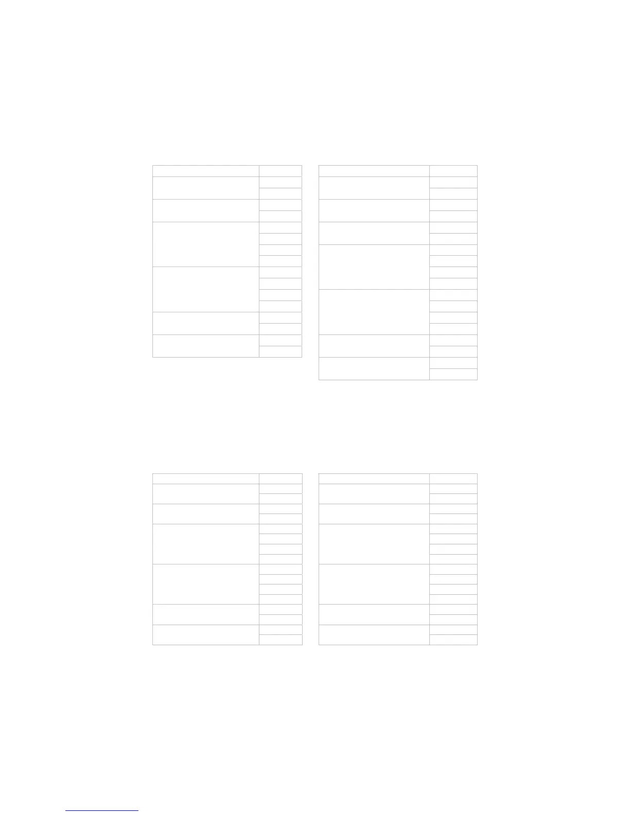
For example, in order to read two words from controller 01 (address 01H) at starting data address 4700H, the command in ASCII mode is:
ASCII mode:
Command message: Response message:
STX ‘:’ STX ‘:’
‘0’ ‘0’
ADR1
ADR0
‘1’
ADR1
ADR0
‘1’
‘0’ ‘0’
CMD1
CMD0
‘3’
CMD1
CMD0
‘3’
‘4’ ‘0’
‘7’
Number of data
(count by byte)
‘4’
‘0’ ‘0’
Starting data address
‘0’ ‘1’
‘0’ ‘9’
‘0’
Content of start address
4700H
‘0’
‘0’ ‘0’
Number of data (counted by
word)
‘2’ ‘0’
‘B’ ‘0’
LRC CHK 1
LRC CHK 0
‘3’
Content of start address
4701H
‘0’
CR ‘6’
END 1
END 0
LF
LRC CHK 1
LRC CHK 0
‘7’
CR
END 1
END 0
LF
LRC check:
LRC check is the added sum from “Address” to “Data content”. For example, 01H + 03H + 47H + 00H + 00H + 02H = 4DH, then take the
complementary of 2, B3H.
Command code to write 1 word: 06H
For example, in order to write 1000 (03E8H) in controller 01 (comm. address 01H) at the starting data address 4701H, the command in ASCII mode
is:
ASCII mode:
Command message: Response message:
STX ‘:’ STX ‘:’
‘0’ ‘0’
ADR1
ADR0
‘1’
ADR1
ADR0
‘1’
‘0’ ‘0’
CMD1
CMD0
‘6’
CMD1
CMD0
‘6’
‘4’ ‘4’
‘7’ ‘7’
‘0’ ‘0’
Starting data address
‘1’
Starting data address
‘1’
‘0’ ‘0’
‘3’ ‘3’
‘E’ ‘E’
Data content
‘8’
Data content
‘8’
‘C’ ‘C’
LRC CHK 1
LRC CHK 0
‘6’
LRC CHK 1
LRC CHK 0
‘6’
CR CR
END 1
END 0
LF
END 1
END 0
LF
Question and Answer IconNeed help?

Do you have a question about the Delta A Series and is the answer not in the manual?

Delta A Series Specifications

General IconGeneral
Input TypeThermocouple, RTD, Analog
Output TypeRelay, Analog
DisplayLED
Power Supply100-240VAC, 24VDC
CommunicationRS-485, Modbus RTU
Dimensions48x48mm, 48x96mm, 96x96mm
SeriesA Series

Summary

Specifications

Input and Operating Voltage

Specifies the required input voltage range and acceptable variations.

Sensor, Control Mode, and Output

Details supported sensors, control methods, and output types.

Parameters List

Operation Mode Parameters

Settings for control status (RUN/STOP), alarm limits, and function lock.

Regulation Mode Parameters

Parameters for PID control (P, I, D, offsets) and ON/OFF hysteresis.

Initial Setting Mode Parameters

Configuration for input sensor type, temperature unit, and range limits.

Operation and Settings

Controller Operation Modes

Switching between Operation, Regulation, and Initial Setting modes.

Heating and Cooling Control

Control Functionality

Explanation of how heating and cooling functions are achieved.

Sensor and Alarm Information

Temperature Sensor Types

List of supported sensor types and their corresponding temperature ranges.

Advanced Functions and Communication

Communication Parameters

Details on RS-485 port, transmission speeds, protocol, and addresses.

Communication Protocol Details

Parameter Register Mapping

List of communication addresses and their corresponding parameters.

Communication Protocol Commands

Terminal Identification and Mounting

Terminal Layouts

Diagrams showing terminal identification for DTA4848, DTA7272, and DTA4896/DTA9648/DTA9696.

Related product manuals