EasyManua.ls Logo

Delta AS01DNET-A User Manual

Delta AS01DNET-A
632 pages
To Next Page IconTo Next Page
To Previous Page IconTo Previous Page
Page #269 background imageLoading...
Page #269 background image
Chapter 8 Load Cell Module AS02LC
8- 15
8_
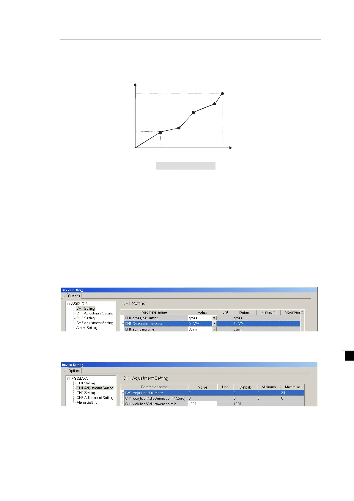
In addition to this two-point adjustment, the load cell also supports adjustments of up to 20 points. A
characteristic curve is shown below.
Digital value
(LSB)
Point 1
Weight
K1000
K10000
K0
1 kg
10 kg
Adjusting multiple points
Point 2
Point 3
Point 4
Point 5
6. Determining theoretical calibration
Theoretical calibration is determined according to the sensor specification in order to input the voltage values
corresponding to various weights. The registers for storing the voltage values are CR#700–739 for CH1 and
CR#740–779 for CH2. After entering the voltage values into the registers, you can use the command set
16#301–302 to execute the calibration.
Example: the sensor specification is 10 kg and its eigenvalue is 2 mV/V. When the sensor is loaded with a 10
kg weight, the output is 10 mV. The theoretical calibration steps are:
Step 1: set the eigenvalue.
Step 2: set the 2-point adjustment; when the sensor is loaded with a 1 kg weight, set the value to 1000.
Step 3: set the voltage calibration for the zero point to 0 (0 mV) in the CR#700/701 registers, and to 1.0 (1
mV) in the CR702/703 registers.
Step 4: enable the calibration function and enter 98 into the command set CR#201.

Table of Contents

Question and Answer IconNeed help?

Do you have a question about the Delta AS01DNET-A and is the answer not in the manual?

Delta AS01DNET-A Specifications

General IconGeneral
BrandDelta
ModelAS01DNET-A
CategoryNetwork Hardware
LanguageEnglish

Summary

Chapter 1 Introduction

1.3 Installation

Covers the procedures for installing AS Series modules, including modules, terminal blocks, and extension cards.

Chapter 2 Digital Input / Output Modules

Chapter 3 Analog Input Module AS04/08AD

3.3 HWCONFIG in ISPSoft

Guides on using HWCONFIG software within ISPSoft for configuring analog modules.

3.4 DIADesigner+ (Hardware Configuration)

Instructions for hardware configuration of analog modules using DIADesigner+ software.

3.5 Troubleshooting

Provides solutions for common issues encountered with analog input modules, including error codes.

Chapter 4 Analog Output Module AS04DA

4.3 HWCONFIG in ISPSoft

Guides on using HWCONFIG software within ISPSoft for configuring the analog output module.

4.4 DIADesigner+ (Hardware Configuration)

Instructions for hardware configuration of the analog output module using DIADesigner+.

4.5 Troubleshooting

Provides solutions for common issues encountered with the analog output module, including error codes.

Chapter 5 Analog Input/Output Module AS06XA

5.3 HWCONFIG in ISPSoft

Guides on using HWCONFIG software within ISPSoft for configuring the AS06XA module.

5.4 DIADesigner+ (Hardware Configuration)

Instructions for hardware configuration of the AS06XA module using DIADesigner+.

5.5 Troubleshooting

Provides solutions for common issues encountered with the AS06XA module, including error codes.

Chapter 6 Temperature Measurement Module AS04/06RTD

6.3 HWCONFIG in ISPSoft

Guides on using HWCONFIG software within ISPSoft for configuring temperature modules.

6.4 DIADesigner+ (Hardware Configuration)

Instructions for hardware configuration of temperature modules using DIADesigner+.

6.5 Troubleshooting

Provides solutions for common issues encountered with temperature measurement modules, including error codes.

Chapter 7 Temperature Measurement Module AS04/08TC

7.3 HWCONFIG in ISPSoft

Guides on using HWCONFIG software within ISPSoft for configuring AS04/08TC modules.

7.4 DIADesigner+ (Hardware Configuration)

Instructions for hardware configuration of AS04/08TC modules using DIADesigner+.

7.5 Troubleshooting

Provides solutions for common issues encountered with AS04/08TC modules, including error codes.

Chapter 8 Load Cell Module AS02LC

8.3 Making Adjustments

Covers procedures for making adjustments to the load cell module, including steps and wizards.

8.4 HWCONFIG in ISPSoft

Guides on using HWCONFIG software within ISPSoft for configuring the load cell module.

8.5 Troubleshooting

Provides solutions for common issues encountered with the load cell module, including error codes.

Chapter 9 Serial Communication Module AS00SCM

9.3 COM mode

Describes the COM modes (Modbus, UD Link, CANopen) available for the AS00SCM module.

9.7 Error Codes

Lists and explains the error codes and troubleshooting procedures for the AS00SCM module.

Chapter 10 Function Cards

Chapter 11 DeviceNet Master Scanner Module AS01DNET-A

Chapter 12 Positioning Module AS02/04

12.4 Troubleshooting

Provides solutions for common issues encountered with positioning modules, including error and state codes.

Chapter 13 IO-Link Communication Module AS04SIL

Chapter 14 High Speed Counter Module AS02HC

14.5 Troubleshooting

Provides solutions for common issues encountered with the high-speed counter module, including error codes.

Related product manuals