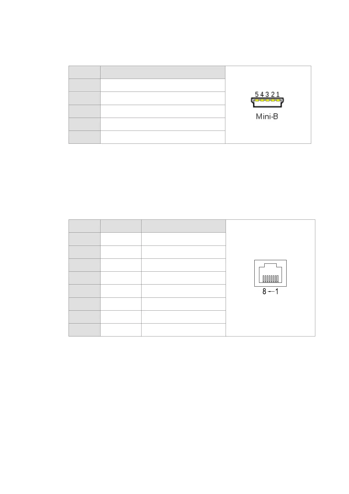
USB port
Pin Function
1
VBUS (4.4–5.25 V)
2
D−
3
D+
4
Ground
5
Ground
Refer to Appendix A : Installing a USB Driver, if it is the first time for AS Series to use USB port to
communicate.
Time to use USB port: uploading/downloading PLC programs, monitoring during calibration and
upgrading firmware.
NOT suggested to use USB port: applications that require a long and un-interruptible
communication.
What to do when a communication failure occurs: unplug any communication connector from the
USB port and then plug the connector back. After that reconnect and try communication again.
Ethernet port
Pin
Signal Description
1
TX+ Transmitting data (positive pole)
2
TX- Transmitting data (negative pole)
3
RX+ Receiving data (positive pole)
4
-- N/C
5
-- N/C
6
RX- Receiving data (negative pole)
7
-- N/C
8
-- N/C
Send Quote Requests to info@automatedpt.com
Call +1(800)985-6929 To Order or Order Online At Deltaacdrives.com
Send Quote Requests to info@automatedpt.com
Call +1(800)985-6929 To Order or Order Online At Deltaacdrives.com
 Loading...