EasyManua.ls Logo

Delta DOP-B10 Series - User Manual

Delta DOP-B10 Series
2 pages
Print Icon
To Next Page IconTo Next Page
Loading...
DOP
-B10
High ColorWide Screen
User-Friendly HMI Products
No.18, Xinglong Rd., Taoyuan City
33068, Taiwan
B10S615 / B10E615 Instrunction Sheet
(1) Preface
Thank you for purchasing DELTA’s DOP-B series. This instruction sheet will be helpful in the installation, wiring and inspection of
Delta HMI. Before using the product, please read this instruction sheet to ensure correct use. You should thoroughly understand all
safety precautions before proceeding with the installation, wiring and operation. Place this instruction sheet in a safe location for
future reference. Please observe the following precautions:
Install the product in a clean and dry location free from corrosive and inflammable gases or liquids.
Ensure that all wiring instructions and recommendations are followed.
Ensure that HMI is correctly connected to a ground. The grounding method must comply with the electrical standard of
the country (Please refer to NFPA 70: National Electrical Code, 2005 Ed.).
Do not disassemble HMI, modify or remove wiring when power is applied to HMI.
Do not touch the power supply during operation. Otherwise, it may cause electric shock.
If you have any questions during operation, please contact our local distributors or Delta sales representatives.
The content of this instruction sheet may be revised without prior notice. Please consult our distributors or download the most
updated version at http://www.delta.com.tw/ia
(2) Safety Precautions
Carefully note and observe the following safety precautions when receiving, inspecting, installing, operating, maintaining and
troubleshooting. The following words, DANGER, WARNING and STOP are used to mark safety precautions when using the
Delta’s HMI product. Failure to observe these precautions may void the warranty!
Installation
Comply with quick start for installation. Otherwise it may cause equipment damage.
Do not install the product in a location that is outside the stated specification for the HMI. Failure to
observe this caution may result in electric shock, fire, or explosion.
Do not install the product in a location where temperatures will exceed specification for the HMI.
Failure to observe this caution may result in abnormal operation or damage the product.
Please note that this equipment has obtained EMC registration for commercial use. In the event
that it has been mistakenly sold or purchased, please exchange it for equipment certified for home
use.
Do not use this product as an alarm device for disaster early warning that may result in personal
injury, equipment damage, or system emergency stop.
Wiring
Connect the ground terminals to a class-3 ground (Ground resistance should not exceed 100).
Improper grounding may result in communication error, electric shock or fire.
Operation
The users should use Delta Screen Editor software to perform editing in Delta's HMI product. To
perform editing and confirming HMI programs without using Delta Screen Editor software in Delta's
HMI product may result in abnormal operation.
To prevent the personal injury and equipment damage, when designing HMI programs, please
ensure that a communication error occurred between Delta’s HMI product and the connecting
controller or equipment will not result in system failure or malfunction.
Please be sure to backup the screen data and HMI programs in case they are lost, accidentally
deleted or worse.
Do not modify wiring during operation. Otherwise it may result in electric shock or personal injury.
Never use a hard or pointed object to hit or strike the screen as doing this may damage the screen
and let the screen has not respond at all, and then cause HMI to work abnormally.
Maintenance and Inspection
Do not touch any internal or exposed parts of the HMI as electrical shock may result.
Do not remove operation panel while power is on. Otherwise electrical shock may result.
Wait at least 10 minutes after power has been removed before touching any HMI terminals or
performing any wiring and/or inspection as an electrical charge may still remain in the HMI with
hazardous voltages even after power has been removed.
Turn the power off before changing backup battery and check system settings after finishing
change. (all data will be cleared after changing battery).
Be sure the ventilation holes are not obstructed during operation. Otherwise malfunction may result
due to bad ventilation or overheating troubles.
Wiring Method
Do not use a voltage that will exceed specification for the HMI. Failure to observe this caution may
result in electric shock or fire.
Remove the terminal block from the HMI before wiring.
Insert only one wire into one terminal on the terminal block.
If the wiring is in error, perform the wiring again with proper tools. Never use force to remove the
terminals or wires. Otherwise, it may result in malfunction or damage.
For the power line that forced to take out, ensure to check wiring again and restart.
Communication Wiring
Comply with communication wiring specification for wiring.
Wiring length should comply with the stated specification for the HMI.
Proper grounding to avoid bad communication quality.
To avoid noise and interference, the communication cable, all power cables, and motor power
cable should be placed in separate conduits.
(3) Pin Definition of Serial Communication
DOP-B10S615 / DOP-B10E615 COM1 Port (Supports Flow Control)
COM Port PIN
Contact
RS-232
1
2 RXD
3 TXD
4
5 GND
6
7 RTS
8 CTS
9
Note: Blank = No Connection.
DOP-B10S615 / DOP-B10E615 COM2 Port (Supports Flow Control)
COM Port PIN
MODE1 MODE2 MODE3
RS-232 RS-422 RS-485
1 TXD+ D+
2 RXD
3 TXD
4 RXD+
5 GND GND GND
6 TXD- D-
7 RTS
8 CTS
9 RXD-
Note1: Blank = No Connection.
Note2: When COM2 port is used for RS-232 flow control, i.e. RTS and CTS signals are used for flow control, COM3 port will become
incapable of being used.
Note3: When COM2 port is used for RS-422 flow control, please refer to the following COM3 Port signals table for pin assignments. The
signals, RTS+, CTS+, RTS- and CTS- shown in brackets are the signals used for flow control.
DOP-B10S615 / DOP-B10E615 COM3 Port
COM Port PIN
MODE1 MODE2 MODE3
RS-232 RS-422 RS-485
1 TXD+(RTS+) D+
2 RXD
3 TXD
4 RXD+(CTS+)
5 GND GND GND
6 TXD-(RTS-) D-
7
8
9 RXD-(CTS-)
Note1: Blank = No Connection.
Note2: When COM2 port is used for RS-422 flow control, please refer to the COM3 Port signals table above for pin assignments. The signals,
RTS+, CTS+, RTS- and CTS- shown in brackets are the signals used for flow control.
DOP-B10E615 Ethernet Interface (LAN)
Ethernet Interface (LAN) PIN
Contact
Ethernet
1 TX+
2 TX-
3 RX+
4
5
6 RX-
7
8
Note: Blank = No Connection.
(4) Parts Names
DOP-B10S615 DOP-B10E615 (Front View)
A
: Power LED Indicator
Lights in green when HMI works normally.
B
: Operation LED Indicator (Blue)
(Note1)
The operation LED indicator blinks in blue when either the communication is carried out or the
data is accessing (please refer to the “Note1” below for explanation).
: Alarm LED Indicator (Red)
The alarm LED indicator blinks in red when one of the alarms is on.
C Touch Screen / Display
NOTE
1. The definition of the operation LED indicator (Blue) can be determined by the users freely.
DOP-B10S615DOP-B10E615 (Rear View)
A Power Input Terminal F Ethernet Interface (LAN)
B
COM2
(It is provided with two LED indicators to indicate
that HMI is in Read or Write status during the
communication process.)
G Memory Card Slot / Battery Cover
C
COM3
(It is provided with two LED indicators to indicate
that HMI is in Read or Write status during the
communication process.)
H USB Host
D COM1 I Audio Output Interface
E USB Slave J System Key
PIN1
PIN1
PIN1
C
B
A
H
E
F
I
A
B
C
D
J
G
Question and Answer IconNeed help?

Do you have a question about the Delta DOP-B10 Series and is the answer not in the manual?

Summary

Product Preface and Introduction

Safety Precautions for HMI Operation

Serial Communication Pin Definitions

COM1 Port RS-232 Pin Definition

Details the pinout for the COM1 port, specifying RS-232 and flow control signals.

COM2 Port RS-232, RS-422, RS-485 Pin Definition

Details the pinout for the COM2 port, supporting RS-232, RS-422, and RS-485 configurations.

COM3 Port RS-232, RS-422, RS-485 Pin Definition

Details the pinout for the COM3 port, supporting RS-232, RS-422, and RS-485 configurations.

HMI Component Identification

Front View Component Identification

Identifies front panel components and indicators such as the Power LED.

Rear View Component Identification

Identifies rear panel connection terminals and interface ports.

HMI Dimensions and Panel Cutout

HMI Technical Specifications

Module Specifications

Details display type, resolution, backlight, MCU, and memory configurations.

Communication Interfaces

Lists specifications for Ethernet, USB, and serial COM ports.

General Specifications

Covers function keys, cooling, safety approvals, voltage, power, and battery life.

Overview

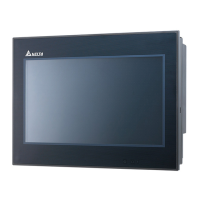
The Delta DOP-B10S615/DOP-B106515 is a Human Machine Interface (HMI) device designed for industrial applications, offering a range of functionalities for control and monitoring. This device is part of Delta's DOP-B10 series, known for its user-friendly interface and robust design.

Function Description:

The DOP-B10S615/DOP-B106515 serves as a visual interface for controlling and monitoring industrial processes. It features a 10.1-inch widescreen TFT LCD with 65,536 colors and a resolution of 1024 x 600 pixels, providing a clear and detailed display of operational data. The device runs on Delta Real Time OS and is powered by a 32-bit RISC Micro-controller, ensuring efficient performance. It includes a Flash ROM of 128 MB for OS system, backup, and user application storage, along with 64 MB of SDRAM and 16 MB of backup memory.

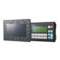
Connectivity is a key aspect of this HMI. It offers multiple communication ports, including COM1 (RS-232), COM2 (RS-232/RS-422/RS-485 with built-in isolated power circuit), and COM3 (RS-232/RS-422/RS-485 with built-in isolated power circuit). These ports allow for flexible integration with various industrial devices and systems. Additionally, it features a USB Host (Ver 1.1) and a USB Slave (Ver 2.0) for data transfer and peripheral connectivity. An SD Card slot supports SDHC for expanded storage. The device also includes an Ethernet Interface (IEEE 802.3, IEEE 802.3u, 10/100 Mbps auto-sensing with built-in isolated power circuit) for network integration.

For audio feedback, the HMI is equipped with a buzzer capable of multi-tone frequencies (2K~4K Hz) at 85dB. An AUX output provides stereo audio. The device also incorporates a built-in perpetual calendar (RTC) for time and date stamping.

Important Technical Specifications:

  • Display: 10.1" Widescreen TFT LCD, 1024 x 600 pixels, 65,536 colors.
  • Backlight: LED Back Light, with a half-life of less than 10,000 hours at 25°C.
  • Processor: 32-bit RISC Micro-controller.
  • Memory: 128 MB Flash ROM, 64 MB SDRAM, 16 MB Backup Memory.
  • Communication Ports: COM1 (RS-232), COM2 (RS-232/RS-422/RS-485 isolated), COM3 (RS-232/RS-422/RS-485 isolated), USB Host (Ver 1.1), USB Slave (Ver 2.0), SD Card, Ethernet (10/100 Mbps isolated).
  • Power Supply: DC +24V (-10% ~ +15%), with built-in isolated power circuit.
  • Power Consumption: 12W.
  • Backup Battery: 3V lithium battery CR2032 x 1, with a life of approximately 3 years or more at 25°C.
  • Operating Temperature: 0°C ~ 50°C.
  • Storage Temperature: -20°C ~ +60°C.
  • Humidity: 10% ~ 90% RH (0~40°C), 10% ~ 55% RH (41~50°C), Pollution Degree 2.
  • Vibration: IEC 61131-2 compliant (5Hz≤f<8.3Hz = Continuous: 3.5mm, 8.3Hz≤f≤150Hz = Continuous: 1.0g).
  • Shock: IEC 60068-2-27 compliant (15g peak for 11 ms duration, X, Y, Z directions for 6 times).
  • Dimensions: 272 x 200 x 61 mm (W x H x D).
  • Panel Cutout: 261.3 X 189.3 mm (W x H).
  • Weight: Approx. 1520g.
  • Safety Approvals: CE, UL, KCC.
  • Waterproof Degree: IP65 / NEMA4.

Usage Features:

The DOP-B10S615/DOP-B106515 is designed for ease of use and integration into industrial environments. Its wide range of communication options allows it to connect with various PLCs, sensors, and other control devices. The isolated power circuits on COM2, COM3, and the Ethernet interface enhance reliability and protect against electrical noise, which is crucial in industrial settings. The USB Host port can provide up to 5V/500mA of power for connecting external devices. The device supports natural air circulation for cooling, eliminating the need for active cooling components. The IP65/NEMA4 rating ensures protection against dust and water ingress, making it suitable for harsh environments. The perpetual calendar function ensures accurate timekeeping for logging and scheduling.

Maintenance Features:

The device is designed for durability and minimal maintenance. The LED backlight has a long half-life, reducing the frequency of replacement. The backup battery, a 3V lithium CR2032, has an estimated life of approximately 3 years or more under normal conditions (25°C), ensuring the retention of RTC data. Regular checks of the power supply voltage are recommended to ensure it stays within the specified range (DC +24V, -10% ~ +15%). For optimal performance and longevity, it is advised to use a power supply with a capacity 1.5 to 2 times the HMI's power consumption. The device's robust construction and compliance with industrial standards for vibration and shock contribute to its long-term reliability. In case of any issues, the manual provides detailed instructions for troubleshooting and maintenance, including guidelines for proper installation and wiring to prevent damage and ensure safe operation. Users are encouraged to consult the latest version of the manual and contact distributors for any updates or specific technical support.

Delta DOP-B10 Series Specifications

General IconGeneral
BrandDelta
ModelDOP-B10 Series
CategoryTouch Panel
LanguageEnglish

Related product manuals