- 8 -
DC power supply
Emergency stop
Circuit protection fuse
The output of the transistor model is “open collector”. If Y0/Y1 is set to pulse output, the
output current has to be bigger than 0.1 A to ensure normal operation of the model.
1. Diode suppression: Used when in smaller power [Figure 17a] [Figure 18a]
2. Diode + Zener suppression: Used when in larger power and frequent On/Off [Figure 17b]
[Figure 18b]
Manually exclusive output: For example, Y2 and Y3 control the forward running and reverse
running of the motor, forming an interlock for the external circuit, together with the PLC
internal program, to ensure safe protection in case of any unexpected errors.
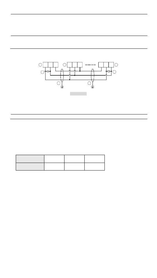
RS-485 Wiring
Figure 16
D+ D- SG D+ D- SG SGD+ D-
3
4
1 2 2
3
4
[ Figure 19 ]
DVP12SA2 provides one set for each COM2 and COM3 [Figure 19], while DVP28SA2 only
provides one set of COM2.
○
1
Master node ○
2
Slave node
○
3
Terminal resistor ○
4
Shielded cable
Note:
1. Terminal resistors are suggested to be connected to master and the last slave with resistor
value of 120Ω.
2. To ensure communication quality, please apply double shielded twisted pair cable (20AWG)
for wiring.
Precision of the RTC (Second/Month)
Temperature
(°C/°F)
0/32 25/77 55/131
Maximum error
(Second)
-117 52 -132
Duration in which the RTC is latched: One week
 Loading...


