- 2 -
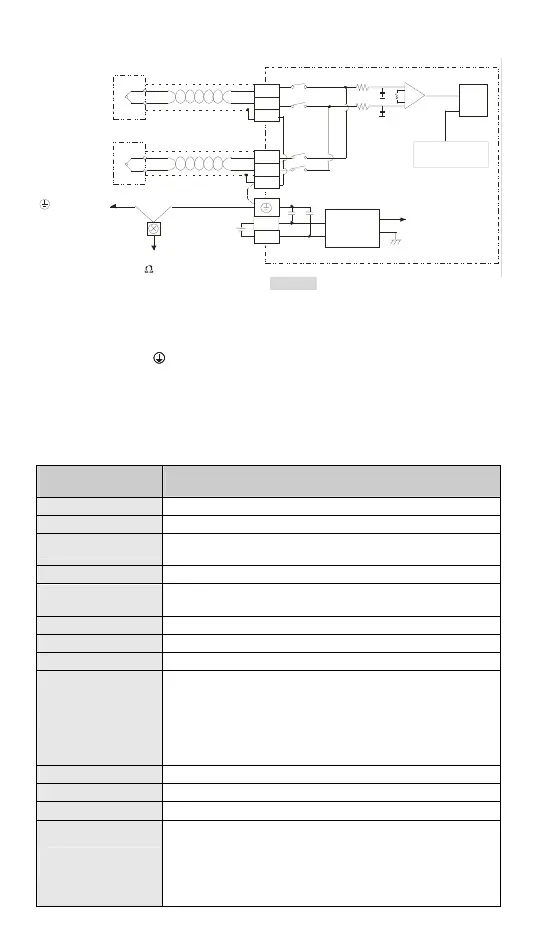
External Wiring
CH1
CH8
L -
L+
+
-
DC/ DC
A+5V
AG
24V
0V
*2
+
-
L -
L+
ADC
AGND
Cold-Junction
Compensation
Shielded
cable *1
Shielded
cable *1
Converter
Thermocouple
Thermocouple
System
gr ounding
Terminal of
power modu le
Class 3 grounding
(1 00 or less)
AGND
SLD
SLD
*3
[Figure 2]
*1: The wiring used for analog input should adopt the connection cable or shielding cable of
thermocouple temperature sensor J-type / K-type / R-type / S-type / T-type / E-type / N-type
and should be separated from other power cable or wirings that may cause interference.
The screw torque of the terminal should be 1.95 kg-cm (1.7 in-lbs).
*2: Please connect the
terminal on both the power module and DVP08TC-H2 to the system
earth point and ground the system contact or connect it to the cover of power distribution
cabinet.
*3: Terminal SLD is a grounding location for noise suppression.
Note: DO NOT wire empty terminal. Use 60/75°C copper conductor only.
Specifications
Temperature
measurement module
Explanation
Power supply voltage 24VDC (20.4VDC ~ 28.8VDC) (-15% ~ +20%)
Analog output channel 8 channels/module
Applicable sensor types
J-type, K-type, R-type, S-type, T-type, E-type, N-type Floating
thermocouple sensor, 0~150mV, ±150mV voltage input.
Range of input temp. See the table in section Temperature / Digital Curve
Range of digital
conversion
See the table in section Temperature / Digital Curve
Resolution 24 bits (0.1°C/0.1°F)
Overall accuracy 0.6% when in full scale within the range of 0 ~ 55°C, 32 ~ 131°F
Response time 200ms × the number of channels
Isolation
Isolation between digital circuits and analog circuits. Isolation
between channels.
500VDC between digital circuits and Ground
500VDC between analog circuits and Ground
500VDC between analog circuits and digital circuits
500VDC between 24VDC and Ground
Digital data format 15 significant bits out of 16 bits are available; in 2’s complement
Average function Yes; available for setting up in CR#10 ~ CR#17; range: K1 ~ K100
Self-diagnosis Upper and lower bound detection/channel
Communication mode
(RS-485)
Supported, including ASCII/RTU mode. Default communication
format: 9600, 7, E, 1, ASCII; refer to CR#36 for details on the
communication format.
Note1: RS-485 cannot be used when connected to CPU series
PLCs.
Note2: The communication format can only be changed via RS-485
 Loading...