Do you have a question about the Delta CANopen DVPCOPM-SL and is the answer not in the manual?
Overview of the DVPCOPM-SL module's capabilities and supported protocols.
Details the communication methods and types supported by the module.
Maps PLC device registers to CANopen network input/output areas.
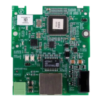
Provides physical dimensions and layout of the DVPCOPM-SL module.
Lists key components and indicators of the DVPCOPM-SL.
Details the pinout and wiring for the CANopen network connector.
Illustrates the standard CAN network setup with terminal resistors.
Explains how to set the node address using DIP switches.
Configures baud rate and communication distance via DIP switches.
Describes the digital display's functions for node address and error codes.
Step-by-step guide for physically connecting the module to the PLC CPU.
Instructions for mounting the module and CPU onto a DIN rail.
Details wiring the CANopen connection port for network communication.
Outlines the process and required equipment for building a CANopen network.
Explains how data is mapped between PLC registers and CANopen devices.
Guides users through setting up the CANopen network using specific software.
Instructions on how to save the current network configuration settings.
Covers compiling WPL programs and controlling the CANopen network.
Explains the fundamental concept of sending SDO, NMT, and Emergency messages.
Details the format and content of SDO request messages for PLC communication.
Defines the structure and codes for NMT service messages.
Outlines the format for emergency request and response messages.
Illustrates practical use cases for SDO, NMT, and Emergency message handling.
Describes how to read the status of slave nodes on the CANopen network.
Explains how to monitor the operational status of the CANopen master module.
Details how to check the overall status of the CANopen network.
Provides the data format for SDO request and response messages.
Demonstrates ladder diagrams for monitoring CANopen network functions.
Explains the indication and correction for the POWER LED status.
Details the RUN LED indications for different operational states.
Describes the ERR LED indications for various error conditions.
Lists codes displayed on the digital screen and their troubleshooting steps.
| Brand | Delta |
|---|---|
| Model | CANopen DVPCOPM-SL |
| Category | Control Unit |
| Language | English |