CANopen Communication Module DVPCOPM-SL
The co
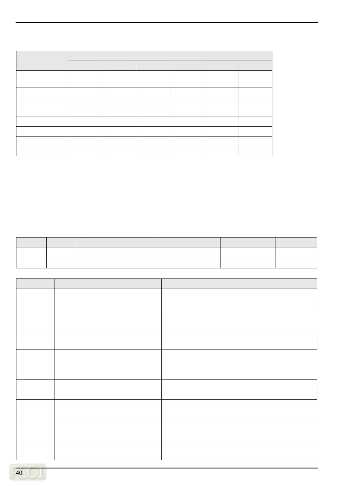
rresponding relations between index H”5002>> subindex H’01 and network nodes are as follows.
Corresponding Network Node
H’5002>>H’01
b15 b14 b13 … … b1 b0
Word 0 Node 15 Node 14 Node 13 … … Node 1 Reserved
Word 1 Node 31 Node 30 Node 29 … … Node 17 Node 16
Word 2 Node 47 Node 46 Node 45 … … Node 33 Node 32
Word 3 Node 63 Node 62 Node 61 … … Node 49 Node 48
Word 4 Node 79 Node 78 Node 77 … … Node 65 Node 64
Word 5 Node 95 Node 94 Node 93 … … Node 81 Node 80
Word 6 Node 111 Node 110 Node 109 … … Node 97 Node 96
Word 7 Node 127 Node 126 Node 125 … … Node 113 Node 112
The corresponding bit is in off status when the nodes in the node list of master module are normal; the corresponding
bit is in on status when the nodes in the node list of master module are abnormal, e.g. Initializing fails or other
abnormality causes slave offline.
6.2 Master Status of CANopen Network
User can read the content value for H’5003>>H’01 to acquire the master module status message of CANopen network
by sending SDO. When master module is at normal work, the content value for H’5003>>H’01 is 0; when there is any
error in master module, the content value for H’5003>>H’01 is the corresponding error code.
Index Subindex Object Name Data Type Access Permission Default
H’00 Entry Unsigned 16 bits RO ---
H’5003
H’01 Status of master module Unsigned 16 bits RO ---
Explanation of the Content value for H’5003>>H’01
Content Value Explanation Actions
F1
Slave has not been added to node list of
CANopen Builder.
Add slave to node list and redownload configuration to
DVPCOPM-SL
F2
In process of downloading configuration
to DVPCOPM-SL.
Wait till the configuration is finished downloading.
F3 DVPCOPM-SL in error status
Redownload configuration and change into a new
DVPCOPM-SL if the error still exists.
F4 Bus-off is detected
Check the wiring for all cables of CANopen network is
proper; ensure all nodes in network are at same baud rate
and finally repower DVPCOPM-SL.
F5
The setting for DVPCOPM-SL node
address is incorrect
The DVPCOPM-SL node address should be set in the
range of 1~127.
F9 Low-voltage detection error
Check and ensure the work power of DVPCOPM-SL is
normal.
FA
The inner part of DVPCOPM-SL
firmware is in error state.
Repower DVPCOPM-SL.
FB
The storage space sending data in
DVPCOPM-SL is full.
Check and ensure bus cable connection is normal and then
repower DVPCOPM-SL.
DVP-PLC Operation Manual
40
 Loading...