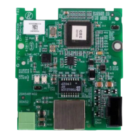
CANopen Communication Module DVPCOPM-SL
2.4 CAN Network Endpoint and Topology Structure
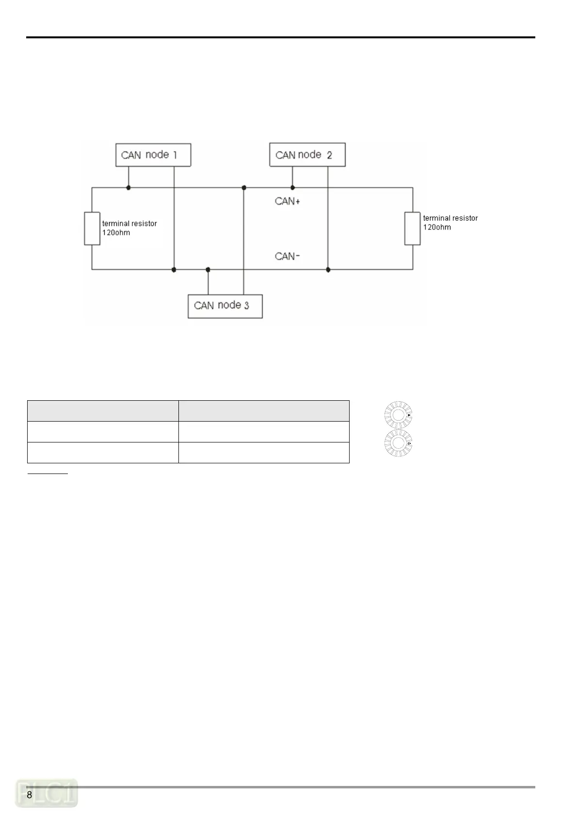
In order to make the CAN communication more stable, the two endpoints of the CAN network are connected to 120
ohm terminal resistors. The topology structure of the CAN network is illustrated below.
2.5 Address Switch
The switch is used on setting up the node address of DVPCOPM-SL on CANopen network. Range: 1 ~ 7F (0, 88 ~ FF
are forbidden).
Switch setting Content
1 ~ 7F Valid CANopen node address
0, 80 ~ FF Invalid CANopen node address
NODE ADDRESS
x16
0
x16
1
Example: If you need to set the node address of DVPCOPM-SL to 26 (1AH), simply switch the corresponding switch of
x16
1
to 1 and the corresponding switch of x16
0
to A.
Note:
Use slotted screwdriver to rotate the switch carefully in case you scratch the switch.
Please set up the node address when the power is switched off. After the setup is completed, re-poser
DVPCOPM-SL.
DVP-PLC Operation Manual
8

 Loading...