Digital/Analog (2D/A) module Voltage output Current output
Connecting to a DVP series PLC
If DVP04DA-S/DVP04DA-S2 modules are connected to a PLC, the modules are numbered
from 0 - 7. 0 is the closest and 7 is the furthest to the PLC. 8 modules is the max and they DO
NOT occupy any digital I/O points of the PLC.
Others
Power supply
Max. rated power consumption 24VDC (20.4VDC ~ 28.8VDC) (-15% ~ +20%), 4W, supply from external power.
Environment
Operation/storage
Operation: 0°C ~ 55°C (temperature); 5 ~ 95% (humidity); pollution degree 2.
Storage: -25°C ~70°C (temperature); 5 ~ 95% (humidity).
Vibration/shock immunity International standards: IEC 61131-2, IEC 68-2-6 (TEST Fc)/IEC 61131-2 & IEC 68-2-27 (TEST Ea)
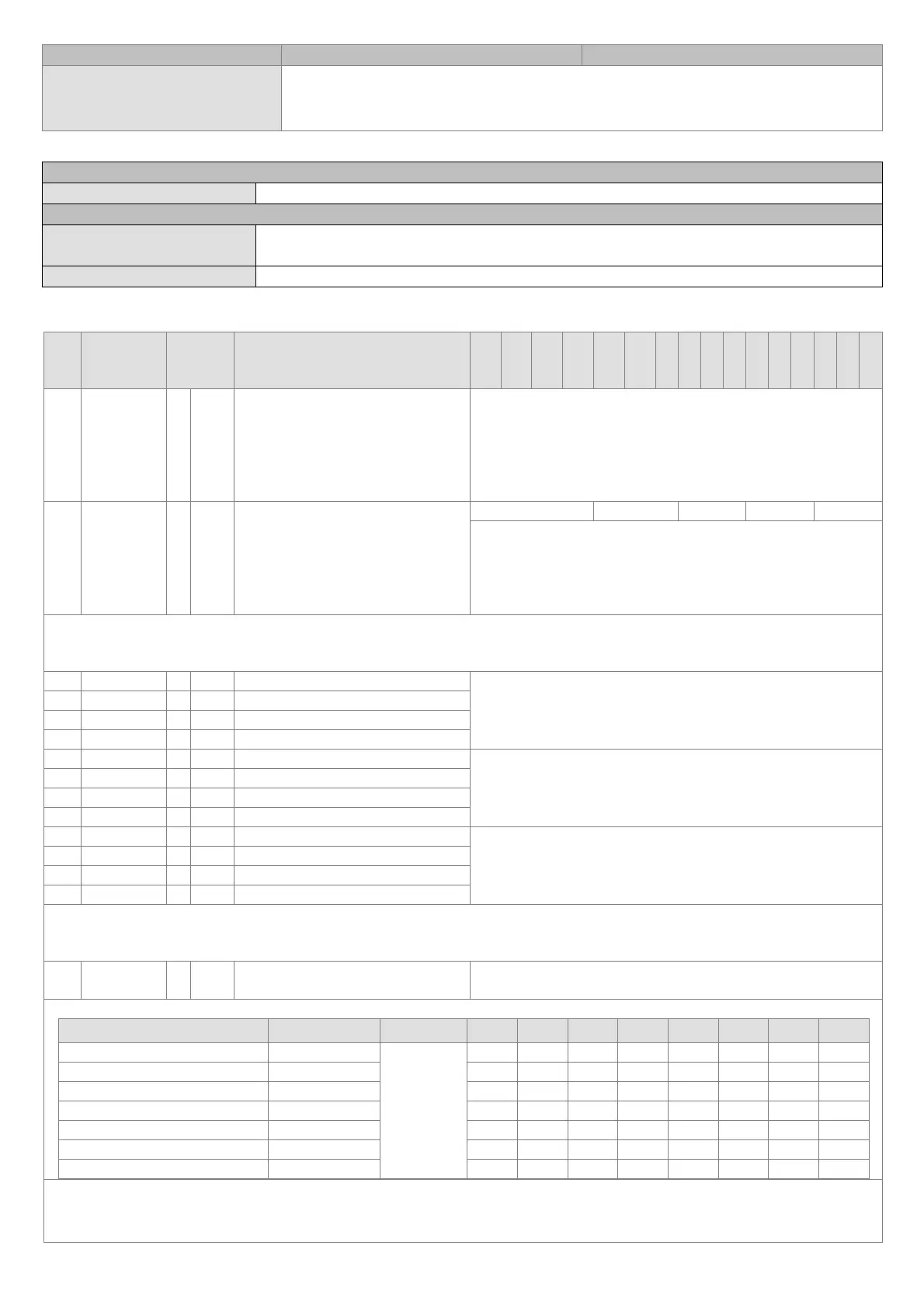
CR (Control Register)
CR#
RS-485
parameters
address
Latched Register name b15 b14 b13 b12 b11 b10 b9 b8 b7 b6 b5 b4 b3 b2 b1 b0
#0 H’4032 ○ R Model type
For system use
Data length: 8 bits (b7 ~ b0)
Model code of DVP04DA-S: H’89
Model code of DVP04DA-S2: H’91
Users can read the model type by means of a program to check if
the extension module exists.
#1 H’4033 ○ R/W Output mode setting
Reserved CH4 CH3 CH2 CH1
Output mode setting: The factory setting is H’0000.
Mode 0: Voltage output mode (0V ~ 10V)
Mode 1: Voltage output mode (2V ~ 10V)
Mode 2: Current output mode (4mA ~ 20mA)
Mode 3: Current output mode (0mA ~ 20mA)
CR#1 is used to set two internal channels working mode of analog output module. Every channel has four modes that can be set
individually. For example: if setting CH1 to mode 2 (b2 ~ b0 = 010), CH2 to mode 1 (b5 ~ b3 = 001), CH3 to mode 0 (b8~b6=000), CH4
to mode 0 (b11~b9=000) It needs to set CR#1 to H’000A.
#6 H’4038 ╳ R/W CH1 output value
The output setting range of channel CH1 ~ CH4 is K0 ~ K4,000.
Default setting is K0 and unit is LSB.
#7 H’4039 ╳ R/W CH2 output value
#8 H’403A ╳ R/W CH3 output value
#9 H’403B ╳ R/W CH4 output value
#18 H’4044 ○ R/W To adjust OFFSET value of CH1
It is used to set the OFFSET value of CH1 ~ CH4.
The setting range is K-2,000 ~ K2,000.
The default setting is K0 and unit is LSB.
#19 H’4045 ○ R/W To adjust OFFSET value of CH2
#20 H’4046 ○ R/W To adjust OFFSET value of CH3
#21 H’4047 ○ R/W To adjust OFFSET value of CH4
#24 H’404A ○ R/W To adjust GAIN value of CH1
It is used to set the GAIN value of CH ~ CH4.
The setting range is K0 ~ K4,000.
The default setting is K2,000 and unit is LSB.
#25 H’404B ○ R/W To adjust GAIN value of CH2
#26 H’404C ○ R/W To adjust GAIN value of CH3
#27 H’404D ○ R/W To adjust GAIN value of CH4
CR#18 ~ CR#27: Please be noticed that GAIN VALUE – OFFSET VALUE=+400
LSB
~ +6,000
LSB
(voltage or current).If the value
difference comes up small (within range), the output signal resolution is then slim and the variation is definitely larger. On the contrast,
if the value difference exceeds the range, the output signal resolution becomes larger and the variation is definitely smaller.
#30 H’4050 ╳ R Error status
Data register to save all error status.
Please refer to error code chart for detail.
CR#30 is error code. Please refer to the following chart.
Error description
Content b15 ~ b8 b7 b6 b5 b4 b3 b2 b1 b0
Power source abnormal K1 (H’1)
Reserved
0 0 0 0 0 0 0 1
Analog input value error K2 (H’2) 0 0 0 0 0 0 1 0
Setting mode error K4 (H’4) 0 0 0 0 0 1 0 0
Offset/gain error K8 (H’8) 0 0 0 0 1 0 0 0
Digital range error K32 (H’20) 0 0 1 0 0 0 0 0
Average times setting error K64 (H’40) 0 1 0 0 0 0 0 0
Instruction error K128 (H’80) 1 0 0 0 0 0 0 0
Note: Each error code will have corresponding bit (b0 ~ b7). Two or more errors may happen at the same time. 0 means normal and 1
means having error.
EX: if the digital input exceeds 4,000, error (K2) will occur. If the analog output exceeds 10V, both analog input value error K2 and K32
will occur.
 Loading...