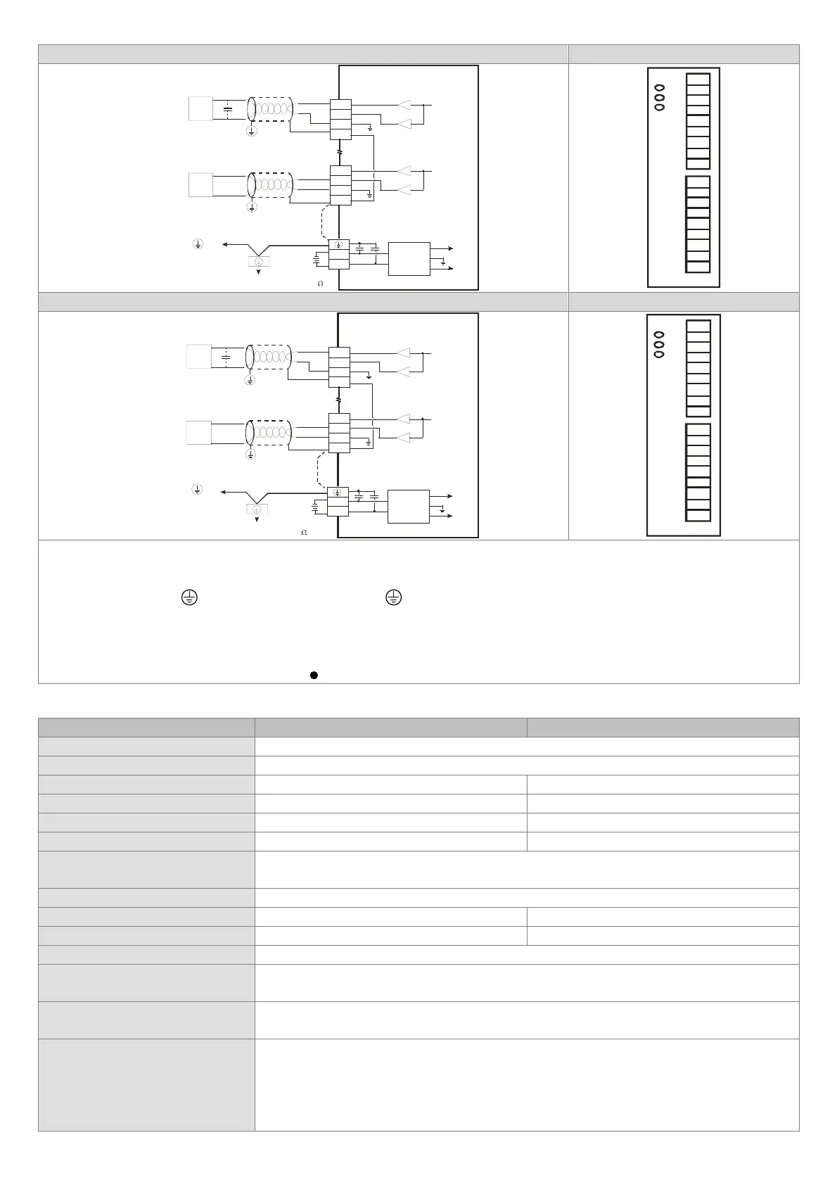
DVP04DA-S Arrangement of the terminals
V+
I+
COM
CH4
Shielded
cable*1
Current output
0mA~20mA
AC motor drive, recorder,
proportioning valve...
CH4
V+
I+
COM
CH1
Shielded
cable*1
Voltage output
0V~+10V
*2
CH1
AC motor drive, recorder,
proportioning valve...
FG
FG
0V
24V
DC24V
+15V
-15V
AG
*3
*4
Connected to on
a power supply module
Ground (Impedance: Less than 100 )
DC/DC
converter
System ground
V+
I+
COM
FG
V+
.
.
I+
COM
FG
V+
I+
COM
FG
I+
COM
FG
V+
DVP04DA-S2 Arrangement of the terminals
V4+
I4+
COM
CH4
0mA~20mA
CH4
V1+
I1+
COM
CH1
0V~+10V
*2
CH1
FG
FG
0V
24V
DC24V
+15V
-15V
AG
*3
*4
Shielded
cable*1
Current output
AC motor drive, recorder,
proportioning valve...
Shielded
cable*1
Voltage output
AC motor drive, recorder,
proportioning valve...
Connected to on
a power supply module
Ground (Impedance: Less than 100 )
DC/DC
converter
System ground
V1+
I1+
COM
FG
V3+
.
.
I2+
COM
FG
V2+
I3+
COM
FG
I4+
COM
FG
V4+
Note 1: Please isolate the analog output cable from other power cables.
Note 2: If noise interferes with the wiring, and makes the ripple voltage of the input terminal of the load connected high, please
connect a 0.1~0.47 μF and 25 V capacitor.
Note 3: Please connect
on a power supply module and on the analog output module to the system ground, and then ground
the system ground or connect the system ground to a distribution box.
Note 4: If there is much noise, please connect the terminal FG to the ground terminal.
※
Use cables with the same length (less than 200 m) and wire resistance of less than 100 ohm.
Warning: DO NOT wire to the empty terminal
.
Specifications
Digital/Analog (2D/A) module Voltage output Current output
Power supply voltage 24VDC (20.4VDC ~ 28.8VDC) (-15% ~ +20%)
Analog input channel 2 channels/each module
Analog output range 0 ~ 10V 0 ~ 20mA
Digital data range 0 ~ 4,000 0 ~ 4,000
Resolution 12 bits (1
LSB
=2.5mV) 12 bits (1
LSB
=5μA)
Output impedance ≦0.5Ω ≧1MΩ
Overall accuracy
0.5% of full scale of 25°C (77°F).
1% of full scale during 0 ~ 55°C (32 ~ 131°F).
Response time 3ms × Number of channels
Max. output current 10mA -
Tolerance carried impedance ≧1KΩ ≦500Ω
Digital data format 16-bit 2’s complement
Isolation method
The analog circuit is isolated from the digital circuit by an optocoupler, but the analog channels
are not isolated from one other.
Protection
Voltage output has short circuit protection but a long period short circuit may cause internal
wire damage and current output break.
Communication mode (RS-485)
Supported, including ASCII/RTU mode. Default communication format: 9600, 7, E, 1, ASCII;
refer to CR#32 for details on the communication format.
Note1: RS-485 cannot be used when connected to CPU series PLCs.
Note2: Refer to Slim Type Special Module Communications in the appendix E of the DVP
programming manual for more details on RS-485 communication setups.
 Loading...