※ DVP04DA-S2 CR#32 communication format settings: for modules with firmware V4.14 or previous versions, b11~b8 data format
selection is not available. For ASCII mode, the format is fixed to 7, E, 1 (H’00XX) and for RTU mode, the format is fixed to 8, E, 1
(H’C0xx/H’80xx). For modules with firmware V4.15 or later, refer to the following table for setups. Note that the original code
H’C0XX/H’80XX will be seen as RTU, 8, E, 1 for modules with firmware V4.15 or later.
b15 ~ b12 b11 ~ b8 b7 ~ b0
ASCII/RTU
exchange low and high byte of CRC
check code
Data format Baud rate
Description
H'0 ASCII H'0 7,E,1*
1
H'01 4800 bps
H'8
RTU,
do not exchange low and high
byte of CRC check code
H'1 8,E,1 H'02 9600 bps
H'2 7,N,1*
1
H'04 19200 bps
H'C
RTU,
exchange low and high byte of
CRC check code
H'3 8,N,1 H'08 38400 bps
H'4 7,O,1*
1
H'10 57600 bps
H'5 8.O,1 H'20 115200 bps
H'6 7,E,2*
1
H'7 8,E,2
H'8 7,N,2*
1
H'9 8,N,2
H'A 7,O,2*
1
H'B 8.O,2
Note *1: This is only available for ASCII format.
Ex: Write H’C310 into CR#32 for a result of RTU, exchange low and high byte of CRC check code, 8,N,1 and baud rate at 57600 bps.
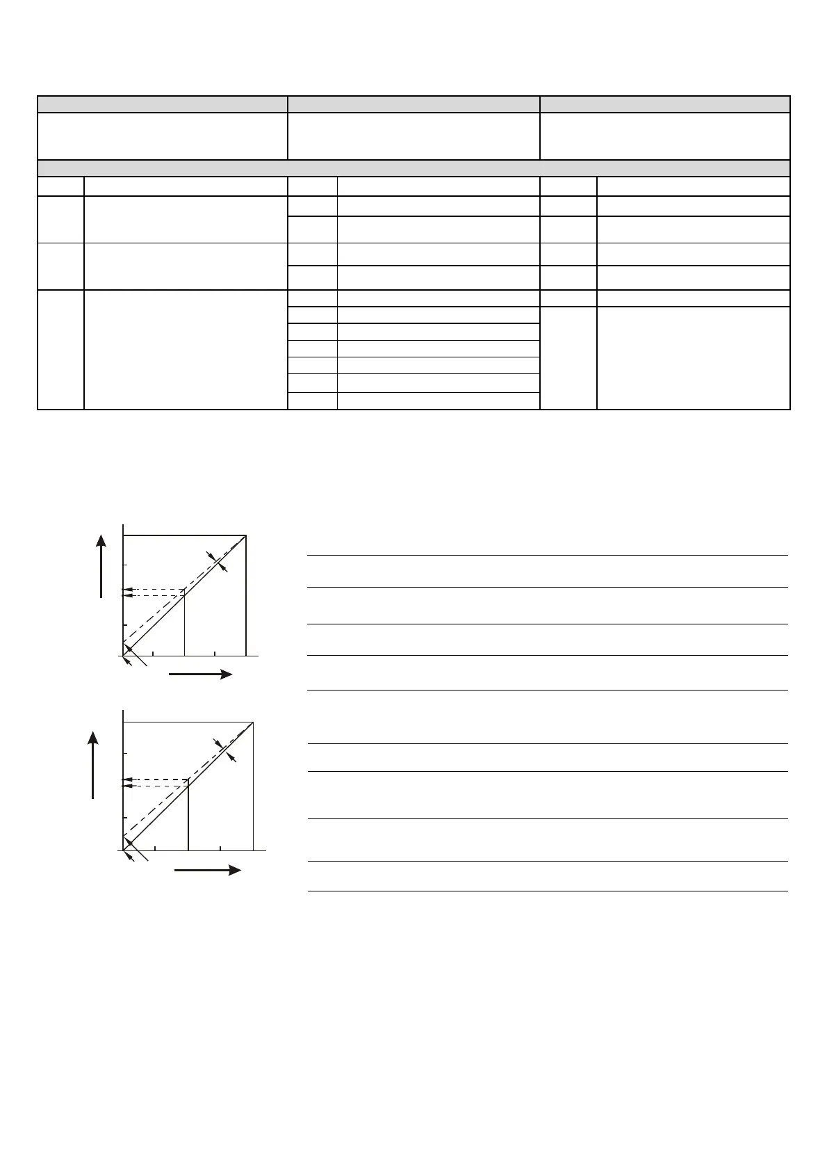
Adjusting D/A Conversion Characteristic
Curves
Voltage output mode:
0
+2,000 +4,000
2V
5V
6V
10V
OFFSET
GAIN
voltage
output
Digital input
mode 0
mode 1
Mode 0 of CR#1: GAIN=5V (2,000
LSB
), OFFSET=0V (0
LSB
).
Mode 1 of CR#1: GAIN=6V (2,400
LSB
), OFFSET=2V (800
LSB
).
GAIN:
The setting range of voltage output value when digital input
value is K2,000 should be 0
LSB
~ +4,000
LSB
.
OFFSET:
The setting range of voltage output value when digital input
value is K0 should be -2,000
LSB
~ +2,000
LSB
.
GAIN-OFFSET: Setting range: +400
LSB
~ +6,000
LSB
.
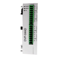
Current output mode:
0
+2,000 +4,000
20mA
OFFSET
GAIN
12mA
10mA
4mA
current
output
digital input
mode 3
mode 2
Mode 2 of CR#1: GAIN=12mA (2,400
LSB
), OFFSET=4mA (800
LSB
).
Mode 3 of CR#1: GAIN=10mA (2,000
LSB
), OFFSET=0mA (0
LSB
).
GAIN:
The setting range of current output when digital input
value is K2,000 should be 0
LSB
~ +4,000
LSB
.
OFFSET:
The setting range of current output when digital input
value is K0 should be -2,000
LSB
~ +2,000
LSB
.
GAIN-OFFSET: Setting range: +400
LSB
~ +6,000
LSB
.
The charts above are D/A conversion characteristic curve of voltage input mode and current input mode. Users can adjust conversion
characteristic curve by changing OFFSET values (CR#18 ~ CR#21) and GAIN values (CR#24 ~ CR#27) depend on application.