- 5 -
04P 06P
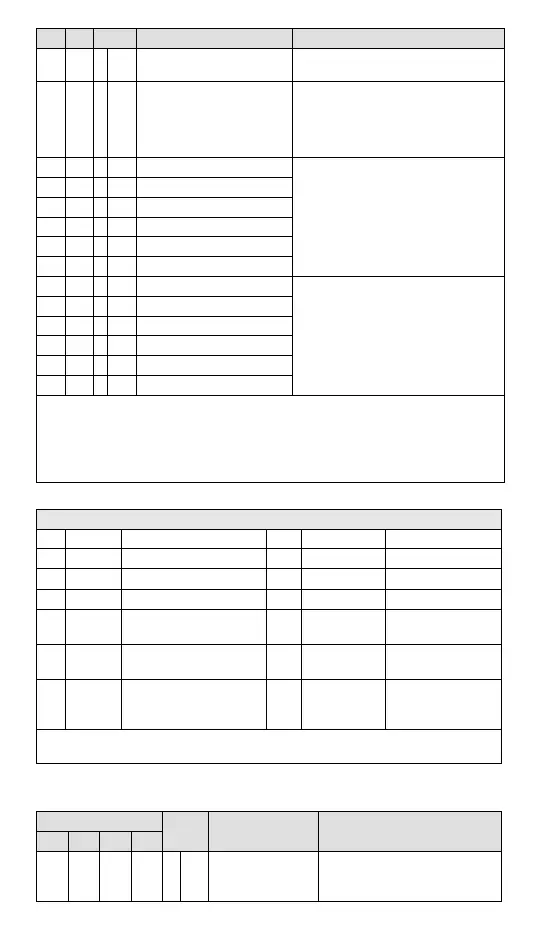
Attrib. Register content Description
#100 #100 O R/W Function: Enable/Disable limit detection
Upper and lower bound detection, b0~b5 corresponds to
CH1 ~ CH6 (0: Disable/ 1: Enable). Default= H’0000.
#101 #101 X R/W Upper and lower bound status
Display the upper and lower bound status (0: Not
Exceeding; 1: Exceeding upper and lower bound value),
b0~b5 corresponds to CH1 ~ CH6 lower bound, b8~b13
corresponds to CH1 ~ CH6 upper bound.
Default =H’0000
#102 #102 O R/W Set value of CH1 upper bound
Set upper bound value. Default = K32000.
#103 #103 O R/W Set value of CH2 upper bound
#104 #104 O R/W Set value of CH3 upper bound
#105 #105 O R/W Set value of CH4 upper bound
#106 O R/W Set value of CH5 upper bound
#107 O R/W Set value of CH6 upper bound
#108 #108 O R/W Set value of CH1 lower bound
Set lower bound value. Default = K-32000.
#109 #109 O R/W Set value of CH2 lower bound
#110 #110 O R/W Set value of CH3 lower bound
#111 #111 O R/W Set value of CH4 lower bound
#112 O R/W Set value of CH5 lower bound
#113 O R/W Set value of CH6 lower bound
Symbols: O: When CR#41 is set to H’5678, the set value of CR will be saved;
X: set value will not be saved
R: able to read data by using FROM instruction
W: able to write data by using TO instruction.
Module Reset: Write H’4352 into CR#0; the action can re-initialize all parameter settings to ensure normal function. Connect only 1
device (preferred) for module reset and then wait 1 sec. to execute power outage.
※ CR#43: Error status value. See the table below:
Description
bit0 K1 (H’1) Power supply error bit7 K128 (H’80) CH5 Conversion error
bit1 K2 (H’2) Reserved bit8 K256(H’0100) CH6 Conversion error
bit2 K4 (H’4) Upper / lower bound error bit9 K512(H’0200) Mode setting error
bit3 K8 (H’8) CH1 Conversion error bit10 K1024(H’0400) Sampling range error
bit4
K16
(H’10)
CH2 Conversion error bit11 K2048(H’0800)
Upper / lower bound
setting error
bit5
K32
(H’20)
CH3 Conversion error bit12 K4096(H’1000)
Set value changing
prohibited
bit6
K64
(H’40)
CH4 Conversion error bit13 K8192(H’2000)
Communication
breakdown on next
module
Note: Each error status is determined by the corresponding bit (b0 ~ b15) and there may be more
than 2 errors occurring at the same time. 0 = normal; 1 = error
PID Control Registers
Note 1: CH5 and CH6 in DVP06PT-E2 do not support PID control.
CR#
Attrib. Register content Description
CH1 CH2 CH3 CH4
#120 #140 #160 #180 O R/W
Set temperature
value
Please set the temperature value
according to proper range of each
sensor type. Default = K0
 Loading...