V1+
I1+
CH1
V4+
CH4
*3
*2
24V
0V
DC24V
+15V
-15V
AG
CH1
1M
AG
1M
250
CH4
1M
AG
1M
250
-10 V~+10 V
-20 mA~+20 mA
COM1
COM4
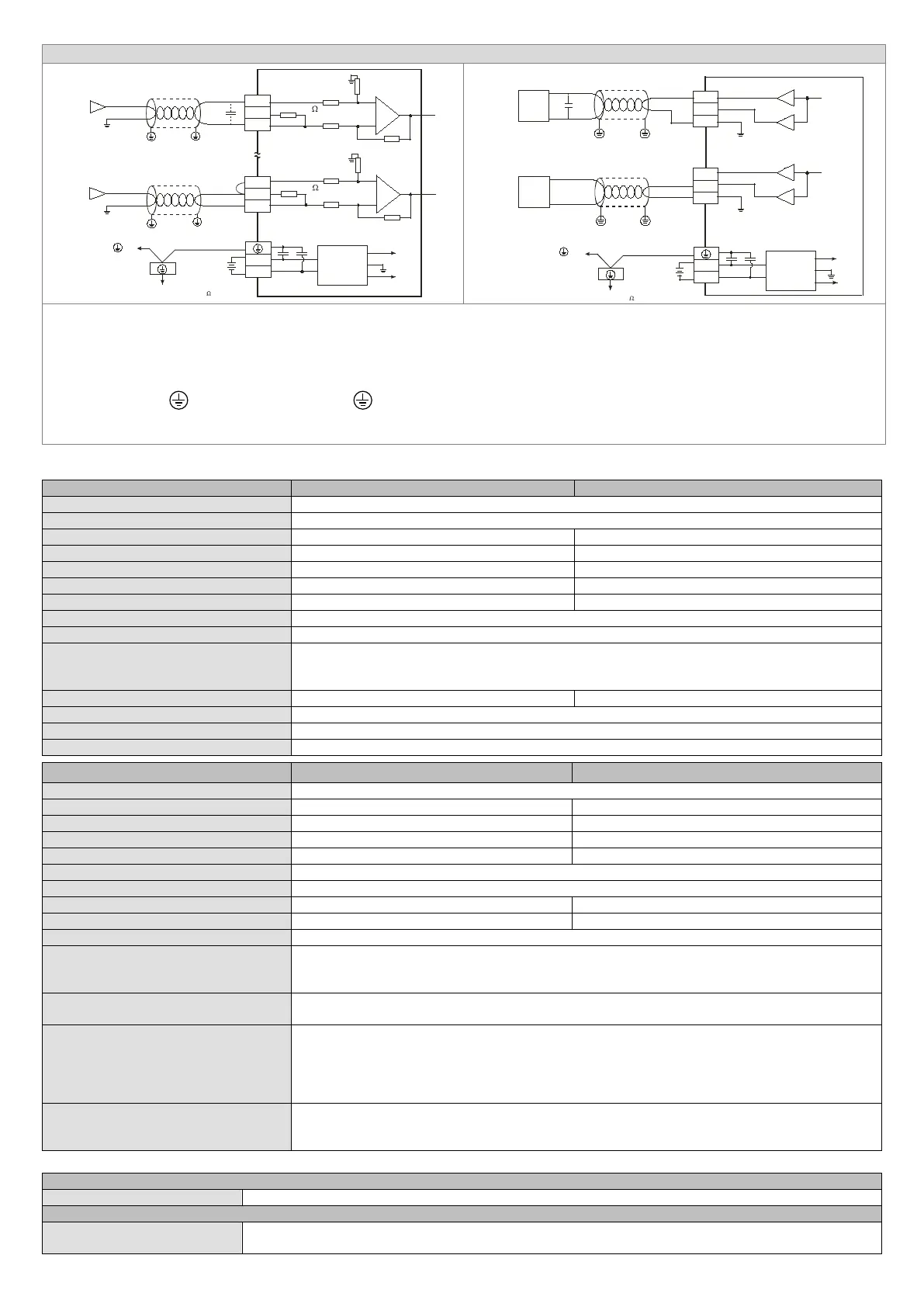
Voltage input
Current input
I4+
*6
Shi elded cable*1
Connected to on
a power supply module
Ground (Impedance: Less than 100 )
DC/DC
converter
System ground
Shi elded cable*1
0V ~ +10V
*5
V5+
I5+
V6+
CH6
24V
0V
DC24V
+15V
-15V
AG
COM
I6+
0mA ~ 20mA
CH5
CH6
CH5
COM
*6
Shi elded cable*4
Current output
AC motor drive, recorder,
proportioning valve...
Shi elded cable*4
Voltage output
AC motor drive, recorder,
proportioning valve...
Connected to on
a power supply module
Ground (Impedance: Less than 100 )
DC/DC
converter
System ground
Note 1: Please isolate the analog input cable from other power cables.
Note 2: If current is connected, the connection between V+ and I+ (the connection between V4+ and I4+) needs to be a short circuit.
Note 3: If ripple voltage results in interference with the wiring, please connect a 0.1~0.47 μF and 25 V capacitor.
Note 4: Please isolate the analog output cable from other power cables.
Note 5: If noise interferes with the wiring, and makes the ripple voltage of the input terminal of the load connected high, please connect a 0.1~0.47 μF and 25 V
capacitor.
Note 6: Please connect
on a power supply module and on the analog input module to the system ground, and then ground the system ground or connect the
system ground to a distribution box.
※
Use cables with the same length (less than 200 m) and wire resistance of less than 100 ohm.
Specifications
Mixed analog/digital (A/D) module
24VDC (20.4VDC ~ 28.8VDC) (-15% ~ +20%)
Input impedance (DVP06XA-S)
Input impedance (DVP06XA-S2)
≧
±0.5% of full scale of 25°C (77°F). ±1% of full scale during 0 ~ 55°C (32 ~ 131°F).
Isolation method
DVP06XA-S: The analog circuit and the digital circuit are grounded together. There is no isolation.
DVP06XA-S2: The analog circuit is isolated from the digital circuit by an optocoupler, but the analog
channels are not isolated from one other.
Yes (CR#2 ~ CR#5 can be set and the range is K1 ~ K20)
Self diagnostic function self detection
Upper bound and lower bound detection per channel
Mixed digital/analog (D/A) module Voltage output Current output
Analog signal output channels
±0.5% of full scale of 25°C (77°F). ±1% of full scale during 0 ~ 55°C (32 ~ 131°F).
Tolerance carried impedance
Isolation method
DVP06XA-S: The analog circuit and the digital circuit are grounded together. There is no isolation.
DVP06XA-S2: The analog circuit is isolated from the digital circuit by an optocoupler, but the analog
channels are not isolated from one other.
Protection
Voltage output has short circuit protection but long period of short circuit may cause internal wiring
damage and current output break.
Communication mode
(RS-485)
Supported, including ASCII/RTU mode. Default communication format: 9600, 7, E, 1, ASCII; refer to
CR#32 for details on the communication format.
Note1: RS-485 cannot be used when connected to CPU series PLCs.
Note2: Refer to Slim Type Special Module Communications in the appendix E of the DVP programming
manual for more details on RS-485 communication setups.
Connecting to a DVP series PLC
When DVP06XA-S/DVP06XA-S2 modules are connected to a PLC, the modules are numbered from
0-7. 0 is the closest to the PLC and 7 is the furthest. The Maximum number of modules is 8 modules and
they do not occupy any digital I/O points of the PLC.
Others
Maximum power consumption
2W at 24VDC (20.4VDC ~ 28.8VDC) (-15% ~ +20%), supplied by external power.
Operation/storage
Operation: 0°C ~ 55°C (temperature); 5 ~ 95% (humidity); pollution degree 2.
Storage: -25°C ~70°C (temperature); 5 ~ 95% (humidity).
 Loading...