- 7 -
○
7
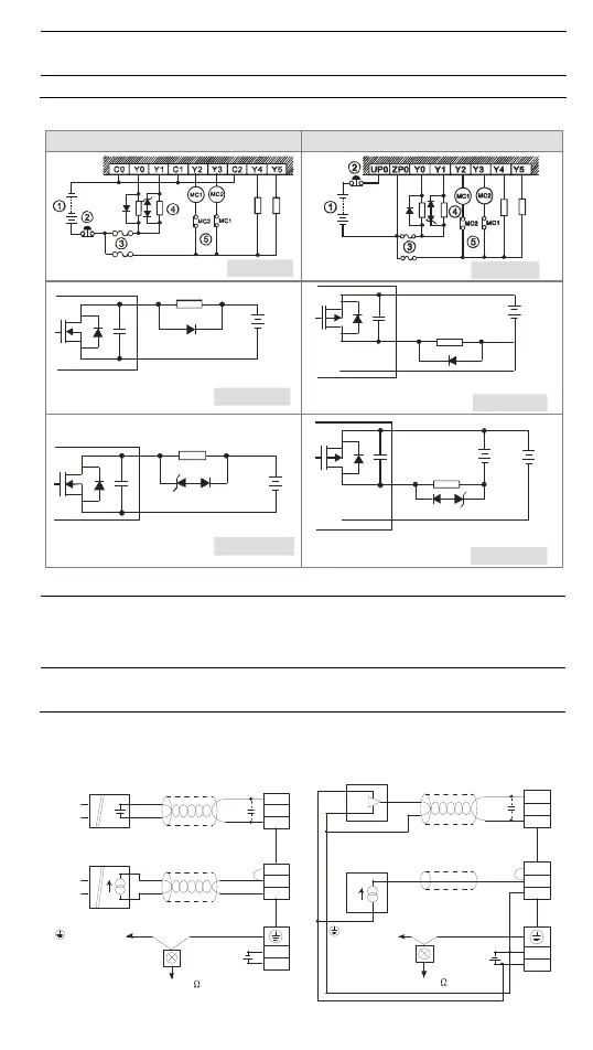
Manually exclusive output: For example, Y3 and Y4 control the forward running and reverse
running of the motor, forming an interlock for the external circuit, together with the PLC
internal program, to ensure safe protection in case of any unexpected errors.
○
8
Neon indicator
○
9
Absorber: Reduces the interference on AC load [Figure 15]
Transistor output circuit wiring
Transistor output (NPN) Transistor output (PNP)
[ F ig u re 17 ]
[ Figure 18 ]
VDC
+
Smaller power
D
[ Figure 19 ]
D: 1N4001 diode or equivalent componen t
C
Y
VDC
+
Smal ler power
D
[ Figure 20]
D: 1N4001 diode or equi valent component
Y
UP
ZP
ZD
D
La rger power and
frequent on/of f
ZD: 9V Z ener, 5W
[ Figure 21 ]
D: 1N4001 diode or equi valent componen t
C
Y
VDC
+
ZD
D
ZD: 9V Z ener, 5W
[ Figure 22 ]
D: 1N4001 diode or equi valent com ponent
ZP
U
VDC
+
Y
VDC
+
Larger power
and
frequent on/off
○
1
DC power supply
○
2
Emergency stop
○
3
Circuit protection fuse
○
4
The output of the transistor model is “open collector”. If Y0/Y1 is set to pulse output, the
output current has to be bigger than 0.1A to ensure normal operation of the model.
1. Diode suppression: Used when in smaller power [Figure 19] and [Figure 20]
2. Diode + Zener suppression: Used when in larger power and frequent On/Off [Figure 21]
[Figure 22]
○
5
Manually exclusive output: For example, Y2 and Y3 control the forward running and reverse
running of the motor, forming an interlock for the external circuit, together with the PLC
internal program, to ensure safe protection in case of any unexpected errors.
A/D External Wiring (For DVP24SV11T2 Only)
Active Passive
Voltage input
Current input
terminal of a
power module
Shielded cable
Shielded cabl e
Grounding (100 or below)100
V0+
I0+
VI0-
CH0
V1+
I1+
VI1-
CH1
24G
+24V
+
-
U
IN
+
-
U
IN
Voltage inpu
Current input
terminal of a
power module
Shielded cable
Shielded c abl e
Grounding (100 or below)100
V0+
I0+
V0-
CH0
V1+
I1+
VI1-
CH1
24G
+24V
-
+
U
IN
-
+
 Loading...