CNC Controller
(1) Préface
Merci davoir acheté ce produit. Avant dutiliser ce produit, lisez attentivement cette fiche dinstructions pour assurer une
utilisation correcte du produit. Gardez cette fiche à portée de main pour pouvoir vous y référer rapidement en cas de besoin.
Avant de terminer la lecture du manuel, suivez ces instructions :
Lemplacement dinstallation doit être exempt de vapeur, de gaz corros if et inflammable.
Lors du câblage, suivez les instructions relatives à laffectation des broches dans le manuel dutilisation et dentretien de
série NC. Assurez-vous que votre contrôleur est correctement mis à la terre.
Pour éviter tout choc électrique, ne démontez pas le contrôleur, ne modifiez pas le câblage ou ne touchez pas
lalimentation électrique lorsque le contrôleur est sous tension.
En cas de problème, consultez le distributeur de votre équipement ou le centre de service à la clientèle Delta. Le contenu de
cette fiche dinstructions peut être révisé sans préavis, contactez le distributeur de votre équipement ou téléchargez la der nière
version sur le site Web de Delta (https://www.deltaww.com/
).
(2) Consignes de sécurité
Installation
Suivez les instructions dinstallation dans le manuel, sinon vous risquez dendommager léquipement.
Nexposez pas le produit à un environnement contenant des vapeurs, des gaz corrosifs, des gaz
inflammables ou dautres matière s étrangères pour réduire le risque de choc électrique ou dincendie.
Câblage
Raccordez les bornes de terre à un système de mise à la terre de classe 3. La résistance de terre ne doit
pas dépasser 100 Ω. Une mise à la terre incorrecte peut entraîner une erreur de communication, un choc
électrique ou un incendie.
Avant lutilisation
Utilisez le logiciel MLC Editor pour configurer correctement les E/S, sinon cela pourrait entraîner un
fonctionnement anormal.
Avant dutiliser la machine, ajustez les para mètres en fonction de lapplication. Si les paramètres ne sont pas
ajustés aux valeurs correctes, cela peut entraîner un dysfonctionnement de la machine ou un fonctionnement
incontrôlé.
Assurez-vous que vous pouvez activer larrêt durgence à tout moment e t évitez de faire fonctionner la
machine sans cette protection.
Opération
Ne modifiez pas le câblage lorsque lappareil est sous tension, sous peine de provoquer un choc électrique
ou des blessures.
Nutilisez pas dobjet pointu pour toucher le panneau. Cela pourrait endommager lécran et entraîner un
dysfonctionnement du contrôleur.
Entretien et inspection
Lorsque lappareil est sous tension, ne démontez pas le panneau du contrôleur et ne touchez pas les pièces
internes, sous peine de provoquer un choc électrique.
Ne touchez pas la borne de terre dans les 10 minutes suivant la mise hors tension, car la tension résiduelle
peut provoquer un choc électrique.
Coupez lalimentation avant de remplacer la batterie de secours et vérifiez les paramètres du sys tème après
le remplacement.
N’obstruez pas les orifices de ventilation pendant le fonctionnement, car une mauvaise ventilation peut
entraîner un dysfonctionnement du contrôleur.
Câblage
Alimentation électrique : pour éviter tout danger, utilisez une alimentation 24 VCC pour le contrôleur et
respectez les spécifications des fils lors du câblage.
Matériaux de câblage : utilisez des fils toronnés et des fils à paires blindées multiconducteurs pour les câbles
de signaux.
Longueur de câblage : la longueur de câble maximale pour les signaux dE/S distants et la communication
DMCNET est de 20 mètres (65,62 pieds) et la longueur maximale de câble pour les autres câbles de signaux
est de 10 mètres (32,8 pieds).
Pour la transmission des signaux dE/S, une alimentat ion 24 VCC est nécessaire pour les E/S du contrôleur
et les E/S distantes.
Câblage du circuit de communication
Câblage DMCNET : les matériaux de câblage doivent être conformes à la spécification standard.
Veillez à ce que le câblage entre le contrôleur et le servo-variateur soit bien raccordé, car des câbles mal
fixés peuvent provoquer un fonctionnement anormal.
(3) Inspection du produit
En cas derreurs demballage ou de dommages pendant le transport, vérifiez soigneusement les éléments énumérés ci -essous :
Produit acheté
Vérifiez le numéro de modèle (voir la section Explication du modèle) sur la plaque signalétique
du contrôleur pour vous assurer qu'il s'agit bien du produit que vous avez acheté.
Vérifiez visuellement si le produit ne présente pas de signes de dommages extérieurs.
Vérifiez qu'il n'y a pas de connecteurs mal fixés ou non serrés.
Si l'une des situations ci-dessus se produit, contactez le distributeur de votre équipement pour résoudre les problèmes.
(1) Preface
Thank you for purchasing this product. Before using this product, please read through this instruction sheet carefully to ensure
the correct use of the product. Keep this sheet handy for quick reference whenever needed. Before finishing reading the manual,
follow the instructions below:
The installation location must be free of all water, corrosive and inflammable gas.
When conducting wiring, please follow the instructions for pin assignment in the NC Series User Manual for Operation and
Maintenance. Make sure that the controller is properly grounded.
To prevent electric shock, do not disassemble the controller, modify the wiring, or touch the power supply when the power
is on.
Please consult your equipment distributor or Delta Customer Service Center if you encounter any problems. The content of this
instruction sheet maybe revised without prior notice, please contact your equipment distributor or download the latest version
from Deltas website (https://www.deltaww.com/
).
(2) Safety Precautions
Installation
Follow the installation instructions in the manual, or it may result in damage to the equipment.
Do not expose the product to an environment containing water, corrosive gas, inflammable gas... etc., or it
may result in electric shock or fire.
Wiring
Connect the ground terminals to class-3 ground system. Ground resistance should not exceed 100 Ω.
Improper grounding may result in communication error, electric shock, or fire.
Before Operation
Use the MLC Editor Software to configure the I/O correctly, or it may result in abnormal operation.
Before the machine starts to operate, please adjust the parameter settings according to the application, or it
may cause abnormal operation or malfunction.
Ensure the emergency stop can be activated at any time, and avoid operating the machine without this
Operation
Do not change the wiring when the power is on, or it may cause electric shock or personnel injury.
Do not use a sharp-pointed object to touch the panel. Doing this may dent the screen and lead to malfunction
of the controller.
Maintenance and Inspection
When the power is on, do not disassemble the controller panel or touch the internal parts, or it may result in
electric shock.
Do not touch the ground terminal within 10 minutes after turning off the power, as the residual voltage may
cause electric shock.
Turn off the power before replacing the backup battery, and check the system settings after the replacement.
Do not block the ventilation holes during operation, as poor ventilation may cause malfunction of the
Wiring
Power supply: to avoid danger, use a 24 V
DC
power supply for the controller and comply with the wire
specification when wiring.
Wiring materials: use stranded wires and multi-core shielded-pair wires for signal cables.
Wiring length: the maximum cable length for remote I/O signals and DMCNET communication is 20 meters
(65.62 feet) and the maximum cable length for other signal cables is 10 meters (32.8 feet).
For I/O signal transmission, a 24 V
DC
power supply is required for the controller I/O and remote I/O.
Wiring of Communication Circuit
DMCNET wiring: the wiring materials should be in compliance with the standard specification.
Make sure the wiring between the controller and servo drive is firmly connected, as loose cables may cause
(3) Product Inspection
In case of packaging mistakes or damages during shipping, carefully check the items listed below:
Purchased product
Check the model number (refer to the Model Explanation section) on the controller
nameplate to make sure that this is the product you have purchased.
Visually check if there are any damages on the exterior of the product.
Check if there are any loose or untightened connectors.
If any of the above occurs, contact your equipment distributor to resolve the issues.
(4) NC Series Controller with Servo Drive
The NC series controller is compatible with Deltas bus servo drive. For detailed specifications, refer to the servo drive user
manuals.
(5) Model Explanation
(1) (2) (3) (4) (5) (6) (7) (8)
N C 3 0 0 B H - M I - A E
(1) Series name
NC2: 2 series controller
NC3: 3 series controller
(5) Model
M: milling
L: lathe
(2) Screen size
0: 8”
1: 10”
(6) Type
I: all-in-one type (integrated with primary and secondary
operator panels)
P: separated type (not integrated with operator panel)
S: separated type (integrated with primary operator panel)
(3)
0: horizontal
1: vertical
(7) Version
A: standard
P: built-in MPG
(4) Series type
B: B series
BH: B series (multi-axis)
(8) Language
Blank: Traditional Chinese
S: Simplified Chinese
(6) Product accessories
Product
accessories
NC300B-MI-A
NC300B-MS-A
NC301B-MS-A
NC310B-MS-A
NC311B-MS-A
NC200B-MI-A
Purpose
One 3-pin connector
● ● ●
Power 24 V
DC
One terminal resistor
● ● ●
DMCNET
Eight sets of M3 screws and nuts
● ● ●
For installation on the machine
Two sets of 15-pin male
connectors with fittings
●
For MPG and SPINDLE terminals
Three sets of 15-pin male
connectors with fittings
● ●
For MPG and SPINDLE terminals
One 5-pin connector
●
For X input contacts of the secondary panel
One 3-pin connector
●
For Y output contacts of the secondary panel
One 2-pin connector
●
●
DC
power input
to the secondary panel
One 12-pin connector
●
●
●
For the CN1 terminal
(7) Mounting and Storage
Ambient Conditions of Storage
Before installation, this product has to be kept in the shipping carton. If the product is temporarily not in use, comply with the
following instructions in order to retain the warranty coverage as well as for future maintenance:
Store this product in a dust-free and dry place.
Store this product in temperature within -20°C to +60°C (-4°F to +140°F).
Store and operate this product in a relative humidity range of 10% - 95% (non-condensing).
Avoid storing the product in an environment containing corrosive and inflammable gas or water.
Avoid storing the product in an environment with vibration that is out of the range specified in the specification.
Ambient Conditions of Installation
Operation temperature: 0°C - 50°C (32°F - 122°F)
To ensure the products performance, the suggested temperature of the operating enviro nment should be under 45°C
(113°F). When the installation site is over 45°C (113°F), install the machine in a distribution board with ventilation and no
overheating risks. Check if the vibration of the machine affects the electrical device of the distribution board.
Pay attention to the items below in order to retain the warranty coverage and for future maintenance of the NC series controller:
The ambient environment should be: free of devices that generate excessive heat; no water, vapor, dust, and oily dust; no
corrosive and inflammable gas or liquids; no airborne dust or metal particles; and the environment should be solid without
vibration and interference of electromagnetic noise.
The temperature and humidity of the installation site are within the range specified in the specification.
Mounting Method and Space
The NC series controller must be installed vertically on a dry and solid platform which complies with the requirement of NEMA.
For better ventilation and cooling, allow sufficient clearance space around the controller (50 mm or 2 inches), and do not block
the ventilation holes. Please note that overheating may result in controller malfunction.
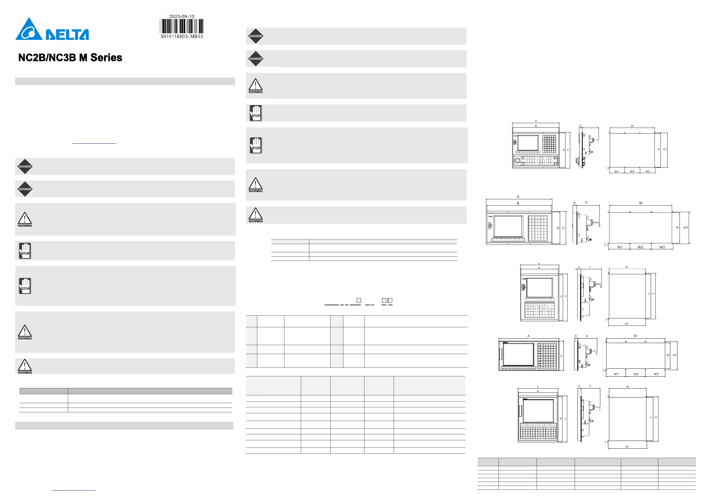
(8) Dimensions
NC300B-MI-A / NC200B-MI-A cut-out / appearance dimensions
NC300B-MS-A cut-out / appearance dimensions
NC301B-MS-A cut-out / appearance dimensions
NC310B-MS-A cut-out / appearance dimensions
NC311B-MS-A cut-out / appearance dimensions
Exterior dimensions
NC300B-MS-A NC301B-MS-A NC310B-MS-A NC311B-MS-A
 Loading...