Chapter 14 Fault Codes and DescriptionsCP2000
14-23
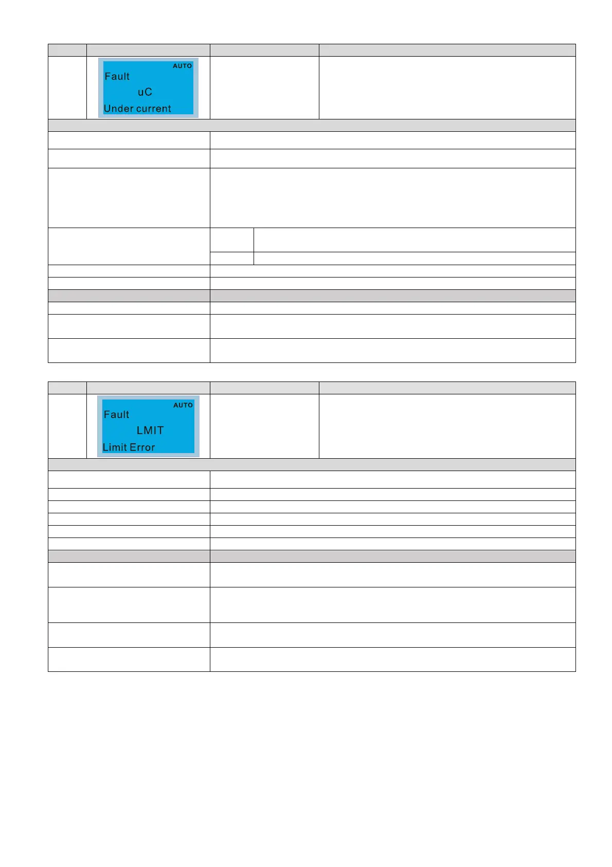
ID* Display on LCD Keypad Fault Name Fault Descriptions
28
Under current
(uC)
Low current detection
Action and Reset
Action level Pr.06-71
Action time Pr.06-72
Fault treatment parameter
Pr.06-73
0: No function
1: Fault and coast to stop
2: Fault and ramp to stop by 2
nd
deceleration time
3: Warn and operation continue
Reset method
Reset condition
Auto
When Pr.06-73=3, uC is a “Warning”. The warning is automatically
cleared when the output current > (Pr.06-71+0.1A).
Manual When Pr.06-73=1 or 2, uC is a “Fault”. You must reset manually.
Record Immediately reset
Active level When Pr.06-71=1 or 2, uC is a “Fault”, and the fault is recorded.
Cause Corrective Actions
Motor cable disconnection Troubleshoot the connection between the motor and the load.
Improper setting of low-current
protection
Reset Pr.06-71, Pr.06-72 and Pr.06-73 to proper settings.
The load is too low
Check the load status.
Check if the motor capacity matches the load.
ID* Display on LCD Keypad Fault Name Fault Descriptions
29
Limit Error (LMIT)
When MIx=45 (forward run limit) or MIx=44 (backward
run limit) act during operation, LMIT error shows.
Action and Reset
Action level MIx=44 (backward run limit) or MIx=45(forward run limit)
Action time Immediately act
Fault treatment parameter N/A
Reset method Manual reset
Reset condition Immediately reset
Record Yes
Cause Corrective Actions
The limit ON/OFF switch is on
incorrect position
Install the limit ON/OFF switch to correct position.
Deceleration time is too long,
causing the motor cannot stop at
limited position
Reduce deceleration time.
Adjust setting values for brake level (Pr.07-01 or the insert position on the brake
unit).
The motor cannot stop due to
over-voltage stall prevention
Reset the over-voltage stall prevention.
Malfunction caused by interference
Verify wiring of the control circuit and wiring/grounding of the main circuit to
prevent interference.