Chapter 12 Descriptions of Parameter Settings | VFD-ED
09 Communication Parameters
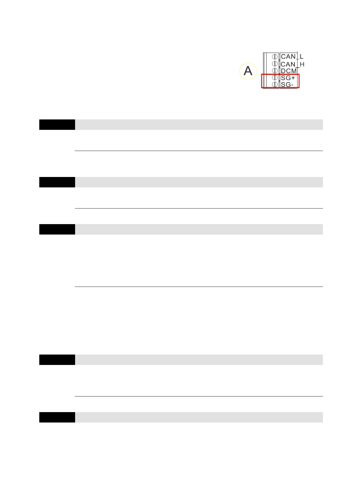
When using the communication interface, the diagram on the
right shows the communication port pin definitions. It is
recommended that you connect the AC motor drive to your PC by
using Delta IFD6530 or IFD6500 as a communication converter.
For details on Modbus communication protocol, see Appendix B.
Modbus Protocol.
: You can set this parameter during operation
Default: 1
Settings 1–254
Sets the communication address for the drive if the AC motor drive is controlled through RS-485
serial communication. The communication address for each AC motor drive must be unique.
Control Mode
Default: 19.2
Settings 4.8–115.2kbps
Sets the transmission speed between the RS-485 master (PLC, PC, etc.) and the AC motor drive.
Transmission Fault Treatment
Control Mode
VF VFPG SVC FOCPG FOCPM Default: 3
Settings 0: Warn and keep operation
1: Fault and ramp to stop
2: Reserved
3: No action and no display
Determines the treatment if a transmission time-out error (such as disconnection) occurs during
communication.
When Pr.09-02 is set to 1 (Fault and ramp to stop), if brake or operation contactor is OFF under
the circumstance that STO or MI40 (Enable drive function) is not deactivated during deceleration,
elevator still runs even brake has engaged (brake wear), and electric arc occurs when operation
contactor is OFF.
Control Mode
Default: 0.0
Settings 0.0–100.0 sec.
0.0: Disable
Sets the communication time-out value.
Control Mode
VF VFPG SVC FOCPG FOCPM Default: 13
Settings 0: 7, N, 1 for ASCII
1: 7, N, 2 for ASCII