Chapter 16 PLC Function ApplicationsC2000 Plus
16-47
Command Function
TMR
16-bit timer
Operand
T-K T0–T159, K0–K32,767
T-D T0–T159, D0–D399
When the TMR command is executed, the designated timer coil will be electrified, and
the timer will begin timing. The contact's action will be as follows when the timing value
reaches the designated set value (timing value >= set value):
NO (Normally Open) contact Closed
NC (Normally Close) contact Open
If the RST command has not been executed, the status of the designated element
will remain unchanged.
Ladder diagram:
X
T5
TMR
K1000
Command code: Description:
LD X0 Load Contact a of X0
TMR
T5 K1000
T5 timer
Set value as K1000
Command Function
CNT
16-bit counter
Operand
C-K C0–C79, K0–K32,767
C-D C0–C79, D0–D399
When the CNT command is executed from Off→On, this indicates that the designated
counter coil goes from no power → electrified, and 1 will be added to the counter's
count value; when the count reaches the designated value (count value = set value),
the contact will have the following action:
NO (Normally Open) contact Closed
NC (Normally Close) contact Open
After the count value has been reached, the contact and count value will both remain
unchanged even if there is continued count pulse input. Please use the RST
command if you wish to restart or clear the count.
Ladder diagram:
X0
C2
CNT K100
Command code: Description:
LD X0 Load Contact a of X0
CNT C2 K100
C2counter
Set value as K100
Command Function
LDP
Start of forward edge detection action
Operand
X0–X17 Y0–Y17 M0–M799 T0–159 C0–C79 D0–D399
-
The LDP command has the same usage as LD, but its action is different; its function is to save
current content, while also saving the detected state of the rising edge of the contact to the
cumulative register.
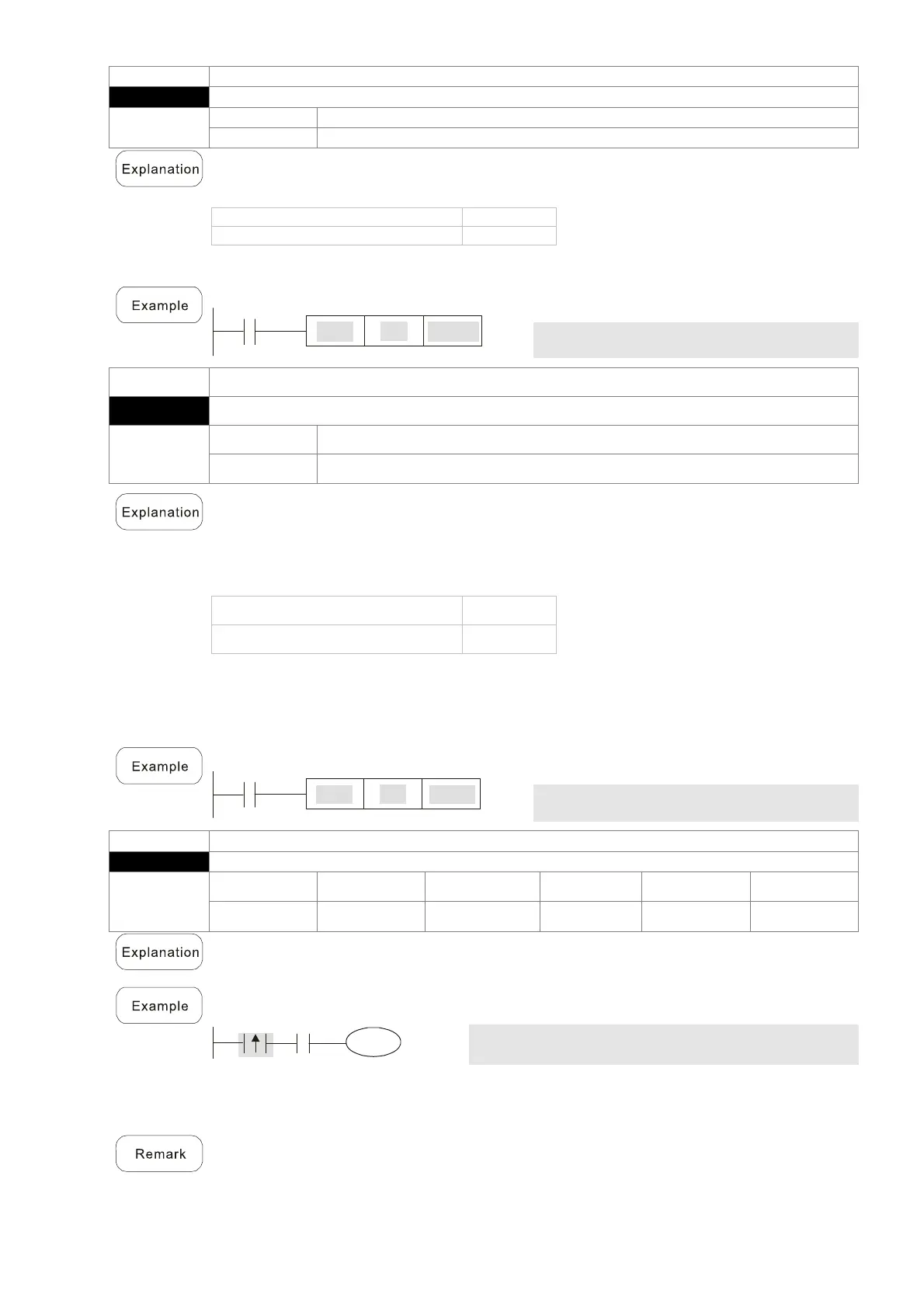
Ladder diagram:
X1
Y1
X0
Command
code:
Description:
LDP X0
Start of X0 forward edge detection
action
AND
X1
Create series connection to
contact a of X1
OUT Y1 Drive Y1 coil
Please refer to the function specifications table for each device in series for the scope of usage
of each operand.
rising edge contact will be TRUE after power is turned on if the rising edge contact is On
before power is turned on to the PLC.