Chapter 16 PLC Function ApplicationsMS300
700
When you execute the CNT command from OFF to ON, switch the designated
counter coil from no power to electrified and add one to the counter's count value.
When the count reaches the designated value (count value = setting value), the
contact has the following action:
N.O. (Normally Open) contact
N.C. (Normally Closed) contact
After reaching the count value, the contact and count value both remain unchanged
even with continued count pulse input. Use the RST command to restart or clear the
count.
C2 counter
Set value as K100
Connect /release a common series contact
MC is the main control initiation command, and any command between MC and MCR
is executed normally. When the MC command is OFF, any command between MC
and MCR acts as follows:
Determination of Commands
The timing value reverts to 0, the coil loses power,
and the contact does not operate.
The coil loses power, and the count value and
contact stay in their current state.
Coil driven by OUT command
Elements driven by SET, RST
commands
They remain in their current state.
MCR is the main control stop command, and is placed at the end of the main control
program. There may not be any contact command prior to the MCR command.
The MC-MCR main control program commands support a nested program structure
with a maximum of only eight levels; use in the order N0–N7. Refer to the following
program example:
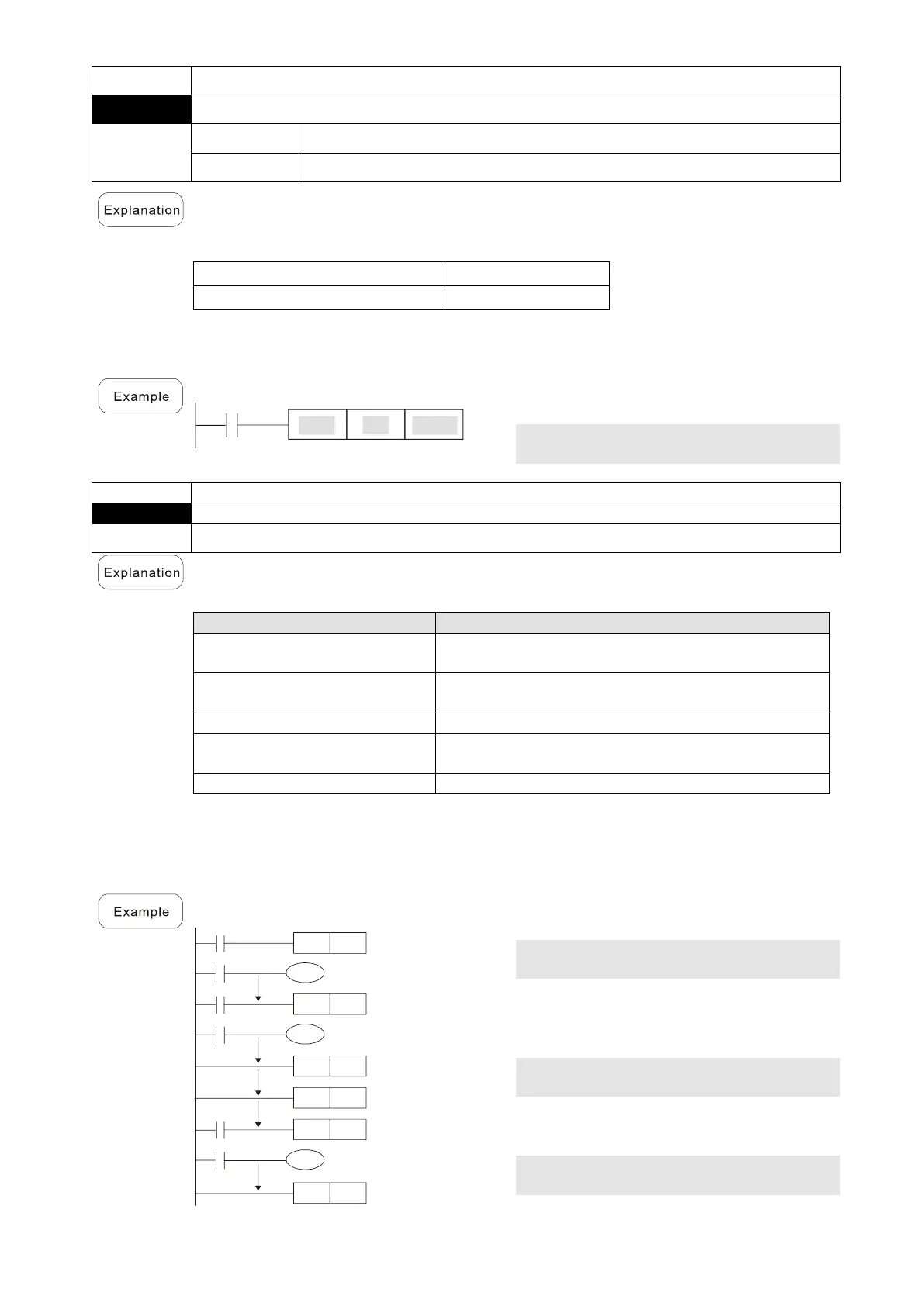
X0
MC
N0
X1
Y0
X2
MC
N1
X3
Y1
MCR
N1
MCR
N0
X10
MC
N0
X11
Y10
MCR
N0
Connection of N0
common series contact
Connection of N1
common series contact
Release N1 common
series contact