Page 30
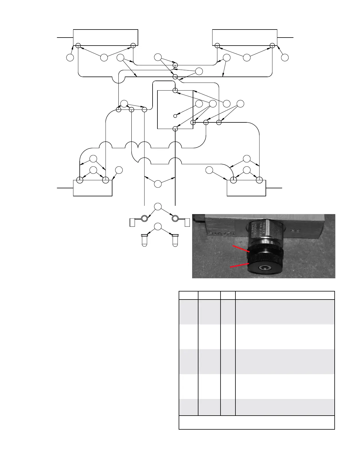
40’ DOWN PRESSURE AND KICK UP HYDRAULIC SCHEMATIC AND OPERATION
DOWN PRESSURE HYDRAULIC PARTS LIST
PORTS
SHOWN IN RED
1
2
3
G
ITEM PART # QTY DESCRIPTION
1
05203
5 #6 FEMALE JIC TO #6 MALE JIC (2X) TEE
2
05243
3 #6 MALE O-RING TO #6 JIC MALE STR
3
07072
2 #6 MALE JIC TEE
4
12369
1 GAUGE HYD 3000PSI - #4 O-RING
5
12677
2 COUPLER RUBBER CAP RED
6
13888
2 QUICK COUPLER #8 O-RING
7
15059
1 DOWN PRESSURE MANIFOLD
8
15082
2 CYLINDER HYD, 3.00 X 6.00
9
15158
8 #8 O-RING X #6 MALE JIC 90°
10
15279
4 375” X 108” HYD HOSE
11
15277
2 .375” X 168” HYD HOSE
12
15695
2 CYLINDER HYD, 3.50 X 14.00
13
15701
4 .375 X 72” HYD HOSE
14
15705
2 .375” X 384” HYD HOSE
Please order replacement parts by PART NO., DESCRIPTION, and
COLOR.
Down Pressure Operation:
The amount of down pressure can be seen on the
hydraulic pressure gauge. Only use as much down
pressure required to keep the coulter at the proper depth.
Do not exceed 1500 PSI.
Activating the Down Pressure
1. After the toolbar has been fully unfolded lock the
hydraulic lever connected to the kick up cylinders
in the tractor to the retract position. This will lower
the toolbar and drop the wings.
2. During operation leave the lever in the locked
position. Hydraulic pressure will now show up on
the gauge.
2. To deactivate the down pressure move the lever to
extend until the wings are kicked up and the toolbar
is raised.
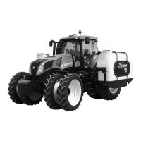
Adjusting the down pressure
1. Loosen the jam nut (A)
2. To increase pressure turn the screw clockwise one
turn at a time. (B)
3. To lower the pressure turn the screw counter
clockwise one turn at a time.
4. Once the desired pressure is reached tighten the
jam nut.
A
B