Do you have a question about the Demco DA66B and is the answer not in the manual?
Crucial warning about potential serious injury or death from improper installation or maintenance.
Explains the meaning and implications of DANGER, WARNING, and CAUTION signal words.
Torque data for standard size bolts (1/4" to 1") across different grade classifications.
Torque data for metric size bolts (M6 to M24) across different class classifications.
Detailed list of part numbers, quantities, and descriptions for the drum brake actuator components.
Detailed list of part numbers, quantities, and descriptions for the disc brake actuator components.
Critical warnings and cautions regarding safe installation practices for the brake actuator.
Instructions for disengaging, inspecting, and replacing the emergency lever and its components.
Specifies the duration of the warranty for different Demco brake system components.
Outlines the process for notifying the manufacturer and options for repair or replacement.
Lists conditions that void the warranty, including misuse, lack of maintenance, and incompatible parts.
Lists items not covered by the warranty, such as normal wear, paint damage, and excess load.
Addresses implied warranties, consequential damages, and purchaser's rights.
States the exclusive nature of the warranty and disclaims responsibility for other claims.
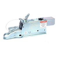
The Demco Model DA66B is a hydraulic surge brake actuator designed for trailers with either two or four wheels. This device operates by utilizing the forward inertia of the trailer towards the towing vehicle to apply brakes on the trailer. The braking force is directly proportional to how hard the brakes are applied on the towing vehicle. A key safety feature is the master cylinder push rod spring assembly, which protects the entire system from hydraulic pressure overload, ensuring safe and reliable operation.
Before installing or using the DA66B, it is crucial to carefully review all instructions provided in the manual. Dealers and distributors are responsible for ensuring that the ultimate user understands these instructions. Failure to follow these guidelines or to properly maintain the braking system after installation can lead to a loss of braking action, which could result in serious injury or death.
When operating the DA66B brake actuator, it is essential to adhere to specific safety precautions. The maximum load rating for the Model DA66B actuator is 6000 lbs. Gross Vehicle Weight Rating (GVWR) and 600 lbs. tongue load. It is critical not to exceed the lowest of these ratings, the rated capacity of the ball and hitch being used, or the trailer's GVWR, to prevent personal injury or death. Additionally, welding on the outer case of the actuator without disassembling it is strictly prohibited. Excessive heat from welding can impair the actuator's proper function, leading to potential safety hazards.
The DA66B actuator comes fully assembled and ready for installation. The installation process involves bolting the actuator to a 3-inch square tongue using two 1/2" x 4-1/2" Grade 5 bolts and 1/2" nylon insert lock nuts. For thin-wall tongues, 3/4" O.D. x 11 gauge wall tubing spacers are required inside the tongue. The bolts should be tightened to 75-80 ft. lbs. of torque, ensuring that the coupler can telescope freely inside the outer case. After securing the actuator, all brake lines must be connected and tightened. The master cylinder should then be filled with DOT 3 or 4 brake fluid.
Bleeding the brake system is a critical step after installation. This can be done using a pressure-type brake bleeder or manually. To manually bleed the system, first remove the two self-tapping screws and lock washers holding the flat emergency lever spring. Then, remove the emergency lever spring. Using short strokes, pull the emergency lever forward to pump the master cylinder until no more air bubbles are visible in the brake fluid. Next, attach a bleeder hose to the bleeder valve on one of the wheels and submerge the other end in a clean, transparent container partially filled with brake fluid. Loosen the bleeder valve one turn and pump the master cylinder with the emergency lever until air bubbles stop leaving the hose. Close the bleeder valve, move to the next wheel, and repeat the process until all brakes are bled. It is important to frequently check the fluid level in the master cylinder (every 4-5 strokes) and refill as necessary to keep it above half full.
Once bleeding is complete, refill the master cylinder to within 1/2 inch of the top and securely attach the cap. Replace the emergency lever spring, lever guide, lock washers, and 5/16" hex head bolts. Any excess brake fluid should be wiped up immediately to prevent paint damage.
Testing the brakes is the final step in installation. Pull the emergency lever forward until it locks into its second notch position (approximately straight up). Attempt to rotate the wheels in a forward direction. If any wheels rotate, the brakes need adjustment. To adjust, release the emergency lever, and set each wheel's brake adjustment up 2 or 3 notches according to the appropriate brake cluster manual. Repeat the test procedure as necessary.
Regular maintenance is essential for the safe and efficient operation of the DA66B actuator. The brake fluid level should be checked frequently, ensuring it is approved, clean, and uncontaminated. The actuator mounting bolts must be secure, and the coupler should be free to telescope inside the outer case. The actuator should be inspected regularly, and any bent, worn, or damaged parts replaced. Operators should always be aware of the braking quality and perform periodic checks as described in the brake owner's manual. Consulting a certified brake specialist for necessary adjustments or repairs is recommended, as failure to do so could result in loss of braking.
Servicing the emergency lever involves specific steps if it becomes applied. It can be disengaged by using a screwdriver to lift the front of the flat emergency lever spring while pulling the lever forward until released. A thorough inspection of the emergency lever, spring, and cable with S-hooks is required, and damaged parts must be replaced. To replace parts, loosen the brake line from the fitting at the back of the master cylinder, taking care not to loosen the fitting itself. Remove the cable S-hook from the emergency lever, and then remove the two bolts and the emergency lever spring. Press the pushrod assembly rearward to allow the emergency lever to pass through and be removed via the cross slot in the top of the outer case. To install a new emergency lever, press the pushrod assembly rearward and hold it while inserting the lever through the cross slot, ensuring it overlaps the front of the pushplate. Install the new emergency lever spring with the bend upward, using two new self-tapping bolts. Install the emergency cable with the S-hook by inserting it through the hole in the emergency lever and squeezing the hook shut. Tighten the fitting and brake line using two wrenches to prevent overtightening in the master cylinder. Finally, add brake fluid if necessary and bleed the brake system as per the installation instructions.
Safety is paramount during maintenance. Ensure adequate ventilation when working on the unit, and never operate the towing vehicle's engine in a closed building due to the risk of asphyxiation from exhaust fumes. Before any work, stop the towing vehicle, set parking brakes, shut off the engine, and remove the ignition key. Confirm all moving parts and attachments have come to a complete stop. Always use safety supports and block wheels; never rely solely on a jack. Use proper tools and extreme caution when making adjustments. Follow the torque chart in the manual for tightening bolts and nuts. Be aware that openings in the skin and minor cuts are susceptible to infection from brake fluid, requiring immediate medical treatment. Replace all shields and guards after servicing. After maintenance, ensure all tools, parts, and service equipment are removed. Prevent grease or oil buildup on the actuator. Use genuine factory replacement parts to maintain original specifications, as unauthorized parts can void warranty and cause damage. Any alterations to the original design will void the manufacturer's liability. A fire extinguisher and first aid kit should be readily accessible during maintenance.
When transporting the unit, always watch for overhead and side-to-side obstructions. Operate equipment to provide maximum visibility, accounting for increased length and weight during turns and stops.
The Demco brake products come with a limited warranty. The DA66B is warranted against defects in materials and workmanship for one year from the purchase date by the original owner, provided it is properly installed, used, and maintained. If used as part of a complete Demco braking system (actuators, brake lines, and back plates), the system is warranted for two years. Any defective part will be repaired or replaced at the manufacturer's option, without charge for parts or labor. The warranty requires timely notification to Dethmers Manufacturing Co.'s customer service department. The warrantor may require the part to be shipped to its factory or an authorized dealer, or may ship a new part for exchange or direct delivery. Coverage is effective only with a copy of the original invoice. The warranty is void if the product is misassembled, damaged, neglected, misused, involved in an accident, or operated contrary to instructions. It does not cover alterations, modifications, abnormal use, or use of incompatible parts. The warranty excludes normal wear and tear, road film or gravel damage to paint, rust damage, and products loaded beyond capacity. It also excludes accessory parts and consequential damages such as loss of use, time, inconvenience, or expenses related to transport, repairs, or lost revenue. Implied warranties expire with the express warranty. This is the exclusive warranty, and no agent can change or add to it. The manufacturer disclaims any other express warranty and is not responsible for direct or indirect damage to personal property arising from contract or tort.
| Output Current | Up to 10 A |
|---|---|
| Protection | IP65 |
| Type | Controller |
| Alternator Frequency | 50-60Hz |
| Operating Temperature | -40°C to +85°C |