EasyManua.ls Logo

Denali CANsmart KTM Series - User Manual

Default Icon
11 pages
Print Icon
To Next Page IconTo Next Page
Loading...
(b)
(d)
(f)
(e)
(g)
(a)
(h)
(c)
Instruction Rev01
0mm
10 20
30
40
50
60
70
80
90
Thank you for choosing DENALI
We know you would rather be riding your bike than wrenching on it, so we go the extra
mile to make sure our instructions are clear and as easy to understand as possible. If
you have any questions, comments, or suggestions don’t hesitate to give our experts
a call at 401.360.2550 or visit WWW.DENALIELECTRONICS.COM
Please Read Before Installing
DENALI products should always be installed by a qualified motorcycle technician. If
you are unsure of your ability to properly install a product, please have the product
installed by your local motorcycle dealer. DENALI takes no responsibility for damages
caused by improper installation. Caution: When installing electronics it is extremely
important to pay close attention to how wires are routed, especially when mounting
products to the front fender, front fork, or fairing of your motorcycle. Always be sure
to turn the handlebars fully left, fully right, and fully compress the suspension to
ensure the wires will not bind and have enough slack for your motorcycle to operate
properly.
Installation Tips
We strongly recommend using medium strength liquid thread locker on all screws and
bolts. It is also important to ensure that all hardware is tightened to the proper torque
specifications as listed in your owner’s manual. For included accessory hardware
please refer to the default torque specifications provided below. Inspect all hardware
after the first 30 miles to ensure that proper torque specifications are maintained.
Hardware Sizing Guide
Not sure what size bolt you have? Use this ruler to measure screws, bolts, spacers, etc.
Remember, the length of a screw or bolt is measured from the start of the “mounting
surface” to the end of the screw, so only include the screw head when measuring
countersunk screws.
M3 10.0 in-lbs - 1.0 Nm
M4
23.0 in-lbs
- 2.5 Nm
M5 44.5 in-lbs 3.5 ft-lbs 5.0 Nm
M6 78.0 in-lbs 6.5 ft-lbs 9.0 Nm
M8 - 13.5 ft-lbs 18.0 Nm
M10 - 30.0 ft-lbs 41.0 Nm
M12 - 52.0 ft-lbs 71.0 Nm
in-lbs
ft-lbs NmBolt Size
0in 1 2
3
What’s In The Box?
DENALIELECTRONICS.COM
CANsmart™ Controller
DNL.WHS.21700
KTM Series
Instruction Manual
(a) CANsmart™ Controller..........................................................Qty 1
(b) 5ft Horn Extension...............................................................Qty 1
(c) 5ft LED Light Extension.........................................................Qty 2
(d) Brake Light Pigtail................................................................Qty 1
(e) Horn Input Harness..............................................................Qty 2
(f) Zip Tie...............................................................................Qty 4
(g) Adhesive Dual Lock..............................................................Qty 1
(h) USB to Micro USB Programming Cable....................................Qty 1
Kit Contents
ONLINE
USER GUIDE
DENALIelectronics.com/KTM
Question and Answer IconNeed help?

Do you have a question about the Denali CANsmart KTM Series and is the answer not in the manual?

Overview

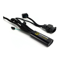
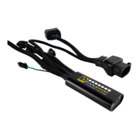
The DENALI CANsmart™ Controller (DNL.WHS.21700 KTM Series) is a sophisticated electronic accessory management system designed for motorcycles, specifically the KTM series. It offers plug-n-play installation and integrated control for up to four accessories, allowing for extensive customization of settings directly from the motorcycle's original controls or through the CANsmart™ Accessory Manager Software.

Function Description:

The CANsmart™ Controller acts as a central hub for managing various motorcycle accessories. It provides four pre-programmed circuits that can independently control two sets of DENALI 2.0 lights, a SoundBomb horn, and a B6 auxiliary brake light. However, its versatility allows users to reassign any accessory to any of the four circuits using the Circuit Function Selector in the CANsmart software. This flexibility enables riders to tailor their accessory setup to their specific needs and preferences.

Important Technical Specifications:

Each circuit is designed to handle up to 10 amps continuously, with a maximum of 25 amps for 25 seconds. The total continuous current draw for the entire system is 25 amps. The device connects to the motorcycle's CAN bus via a 6-pin female diagnostic port, typically located under the rider's seat. Power is supplied directly from the battery, with a fuse holder for protection. The controller features a micro USB port for programming and diagnostics.

Usage Features:

Auxiliary Lights (Two Circuits):

The two auxiliary light circuits offer independent adjustment of high and low beam brightness, controllable via the vehicle's trip switch. Key features include:

  • Brightness Control: Day and night intensity can be adjusted from 0% to 100%.
  • "Flash to Pass" Function: Strobes auxiliary lights when the high beam switch is pulsed.
  • "Strobe When Horn Active" Function: Strobes auxiliary lights when the horn is sounded.
  • "Off When Turn Signal Active" Function: Can be configured to turn off auxiliary lights on the corresponding side when a turn signal is active, enhancing visibility of the turn signal. This feature works best with left/right split light wiring.
  • "Inverse Flashing When Hazards Active" Function: Provides an inverse flashing pattern when hazard lights are engaged.
  • Modulation: Allows for adjustable light modulation.
  • Three-Wire Dimming Mode: Can be disabled for two-wire auxiliary LED lights to ensure proper dimming operation.
  • Left/Right Split Lights: Supports wiring LED lights to operate independently on the left and right sides of the motorcycle, enabling advanced turn signal cancellation features.

Auxiliary Brake Light (One Circuit):

The brake light circuit transforms a simple 2-wire brake light into a "smart brake light" with advanced functionalities:

  • Running Light Intensity: Adjustable from 0% to 100%.
  • Brake Light Intensity: Adjustable from 0% to 100%.
  • Multiple Flash Patterns: Includes "Solid on braking," "Brake Applied Flashing (Continuous)," "Brake Applied Flashing (California legal)," "Flash on Emergency Stop," and "Flash on Rapid Engine Braking."
  • Deceleration Activated Braking: Automatically activates braking functionality based on deceleration.
  • Adjustable "Brake Flashing Travel Speed" and "Deceleration activated braking sensitivity."

Auxiliary Horn (One Circuit):

The horn circuit simplifies the addition of an auxiliary horn, eliminating the need for a separate relay and dedicated wiring harness.

  • Horn Enabled: Activates the auxiliary horn.

Accessory/Ignition Supply (One Circuit):

This circuit provides a simple switched 12V power source for an accessory of choice.

  • Time-out Function: Adjustable from 0 to 60 seconds, determining how long the accessory circuit remains on after the motorcycle's ignition is turned off. The 3rd "data" wire turns off instantly with ignition.

Turn Signals (One Circuit):

The turn signal circuit enables the addition of auxiliary turn signals without tapping into the factory turn signal harness.

  • Running Light Intensity: Adjustable from 0% to 100%.
  • Turn Signal Intensity: Adjustable from 0% to 100%.

Run/Brake/Turn Light (One Circuit):

This circuit supports auxiliary run/brake/turn signals with flash patterns, without tapping into the factory turn signal or brake harness.

  • Running Light Intensity: Adjustable from 0% to 100%.
  • Brake Intensity: Adjustable from 0% to 100%.
  • Turn Signal Intensity: Adjustable from 0% to 100%.
  • Flash Patterns: Includes "Flash on Emergency Stop" and "Flash on Rapid Engine Braking."

Heated Gear (One Circuit):

The heated gear circuit works in conjunction with the motorcycle's factory heated grip settings.

  • Adjustable Power Level: The temperature of the heated gear can be adjusted from 0% to 100% for each stage.

KTM Dongle:

The KTM dongle unlocks additional features in the ABS control unit and the ECU, allowing the motorcycle to remember settings without needing to reset the ABS and MTC every time the motorcycle is restarted. Additional features include:

  • ABS Mode: Offroad
  • MTC Mode: Track/Offroad
  • ECU Mode: 80 Octane

Software Control:

The CANsmart™ Accessory Manager Software is available for Windows and Mac operating systems. It provides a graphical interface for configuring all circuit functions and settings. Users can select circuit functions from a drop-down menu and adjust parameters like intensity, flash patterns, and time-outs.

Motorcycle Control (KTM 1290):

For KTM 1290 models, auxiliary lights are controlled via the factory left-hand side handlebar combination switch using the "Up," "Down," and "Turn Signal Cancel" buttons. Specific actions include:

  • Auxiliary Light Set On/Off: Press and hold turn signal cancel button for 3 seconds.
  • Adjust Intensity: Hold "Up" or "Down" button for 3 seconds, then use "Up" & "Down" buttons to adjust intensity in 10% increments.
  • Sound Auxiliary Horn: Press the vehicle's original horn button.
  • Activate Auxiliary Brake Light: Apply vehicle's front or rear brakes (can be set to flash upon deceleration).
  • Activate Auxiliary Turn Signals: Activates vehicle's original left or right turn signals.
  • Activate Heated Gear/Adjust Heat: Activates and changes power level of vehicle's original heated grips.

Motorcycle Control (KTM 890):

For KTM 890 models, control is simplified due to variations in the factory wiring harness.

  • Auxiliary Horn: Press vehicle's original horn button.
  • Auxiliary Brake Light: Apply vehicle's front brakes (can be set to flash upon deceleration).
  • Heated Gear: Activate vehicle's original heated grips.
  • Adjust Heat: Change the power level of the vehicle's original heated grip.
  • Limitations: Auxiliary Light One & Two Dimming and ON/OFF functions are not available from bikes factory controls (must be set using software). Turn signal circuit function not available. Cancel auxiliary lights with turn signal feature not available. Flash auxiliary lights as turn signal feature not available. Auxiliary brake light activates with front brake lever only.

Maintenance Features:

Diagnostics Window:

The software includes a Diagnostics Window accessible from the main menu, providing an overview of system power consumption, battery/CAN bus voltage, and device temperature.

  • Output Circuit Test: Each circuit can be tested by sliding a slider, allowing users to verify functionality. Horn and Accessory circuits can only be turned on at 100% intensity during testing.
  • Status Indicator Light Key: The CANsmart controller features an LED status indicator light next to the micro USB programming port. This light displays various colors and flash patterns to indicate the system's status and potential faults. The manual provides a key to interpret these indicators and offers corresponding solutions, such as:
    • Solid Green: Normal operation (ignition ON/OFF).
    • Quick Flashing Green: Bootloader Mode (during firmware upgrade).
    • Solid Red: Recovered from an unexpected failure.
    • Flashing Red: At least one channel's electronics fuse has been tripped, or application firmware is corrupt.
    • Solid Green & Flashing Red: Device has been deactivated.
    • Flashing Red & Flashing Green: Data/configuration fault (missing CAN bus data).
  • Online Troubleshooting Guide: A comprehensive troubleshooting guide is available on the DENALIelectronics.com/KTM website for the most up-to-date information.

Installation Tips:

  • Always use medium strength liquid thread locker on all screws and bolts.
  • Ensure all hardware is tightened to proper torque specifications (refer to owner's manual or provided default specifications).
  • Inspect all hardware after the first 30 miles.
  • When routing wires, pay close attention to avoid binding, especially near the front fender, fork, or fairing. Turn handlebars fully left and right, and fully compress suspension to ensure adequate slack.
  • Place the fuse holder in an easily accessible location for convenient service.

The DENALI CANsmart™ Controller is a robust and highly customizable system designed to enhance the functionality and safety of KTM motorcycles by providing integrated control over a wide range of accessories.

Denali CANsmart KTM Series Specifications

General IconGeneral
BrandDenali
ModelCANsmart KTM Series
CategoryController
LanguageEnglish

Related product manuals