14
FT & Super Six SP20001_REV_4
5RXWLQH0DLQWHQDQFH
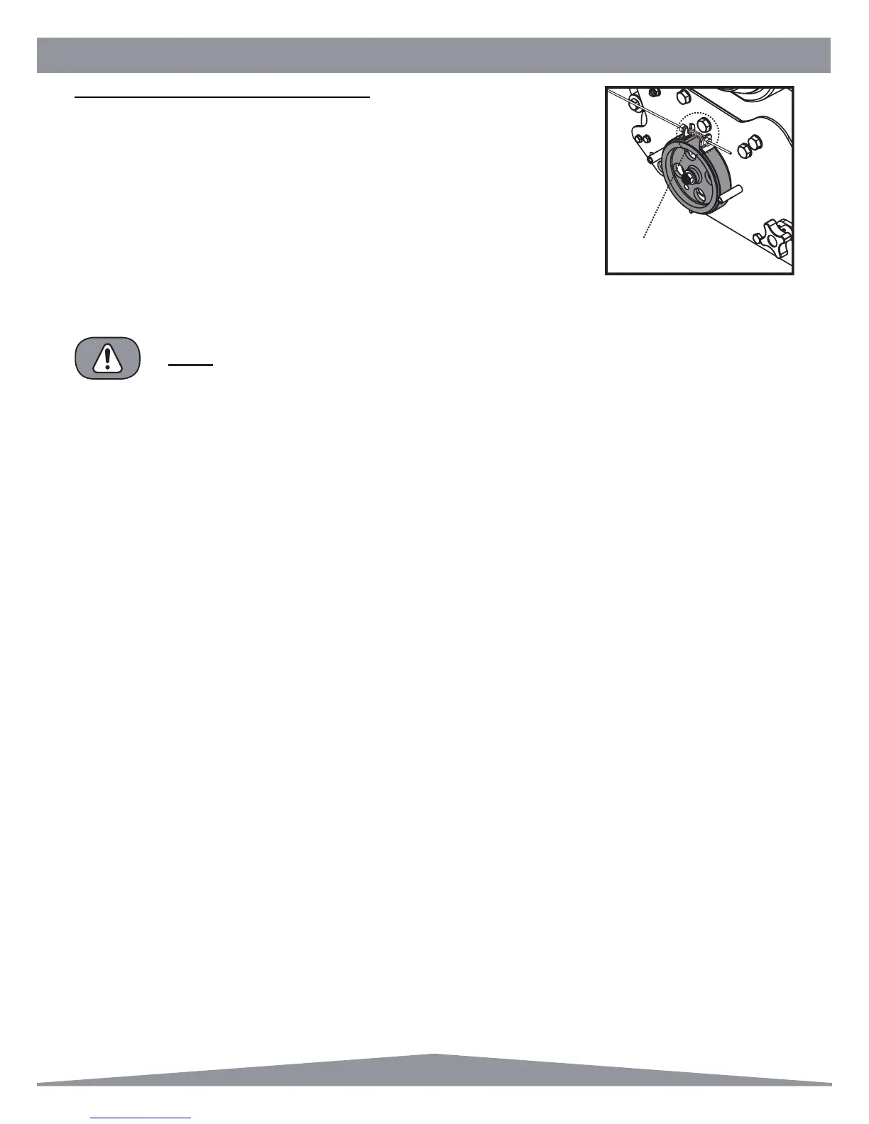
%5$.(%$1'$'-8670(175HDU$[OH'ULYH
The brake band assembly is mounted on the end of the rear axle spindle on the right
hand side of the machine. The assembly comprises a cast iron drum inner member,
which is stopped or braked with a lined steel brake band. This operates dry and no
lubrication of any kind is required.
Adjustment is provided for tightening the band on the inner member should this be
necessary through wear. The procedure to take up any slack is as follows :-
1. Remove the clutch cover by unscrewing the two hexagon headed screws seen on the
outside of the cover.
2. Unscrew the lock nut on the adjuster screw situated between the two clutch band lugs.
ENSURE THE LOCK NUTS ARE TIGHT AND SECURE AND CHECK OPERATION IS
SATISFACTORY BEFORE REPLACING THE CLUTCH COVER AND SCREWS.
NOTE
$GMXVW+HUH
$GMXVWPHQWRIWKHEUDNHEDQGFDQEHVHWWRVXLW\RXUSUHIHUHQFHEXWDOZD\VHQVXUHWKDWWKHUHLVVXI¿FLHQWIUHHSOD\VRWKDW
when the engine revs are increased the machine does not move in any way until the lever is pulled up.
On some models there is adjustment on the handle grip itself to allow any wear to be taken up.