Do you have a question about the Denon AVR-700RD and is the answer not in the manual?
Essential safety warnings and cautions for using the receiver.
Important guidelines for proper operation and placement.
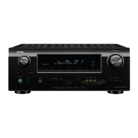
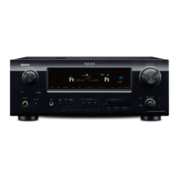
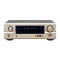
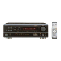
Overview and initial setup information for the AV receiver.
Detailed guide for connecting all necessary audio, video, and speaker components.
Setup and basic usage of the remote control.
Comprehensive guide to using the receiver's playback, surround, and tuning features.
Essential setup steps before starting playback operations.
How to select sources and adjust volume, balance, bass, and treble.
Monitoring a different audio source while playing video.
Temporarily turning off audio output for convenience.
Connecting headphones and adjusting settings for private listening.
Guide for recording audio signals to external devices like tape decks.
Understanding information displayed on the unit's front panel.
Selecting and configuring various surround sound modes.
Detailed guide for tuning and managing radio stations.
Adjusting AM/FM tuning increments for precise station selection.
Automatically scanning and storing FM radio stations.
Methods for automatically finding radio stations.
How to manually tune into specific radio frequencies.
Storing favorite radio stations for quick access.
Accessing stored radio stations.
Feature that retains previous settings upon power off.
Common issues and solutions for receiver operation.
Technical details and performance characteristics of the unit.
Visual guide to internal wiring for maintenance.
Step-by-step instructions for disassembling the unit.
Diagrams for testing and measuring internal circuits.
Diagram and notes for FM signal measurement procedures.
Diagram and notes for audio section measurements.
Procedure to reset the unit's memory to factory defaults.
Pin assignments and functions for integrated circuits.
Block diagrams illustrating IC functionality.
Details for specific integrated circuits like LM7001, LC78212.
Information on various ICs, protectors, and other components.
Identification of transistors, diodes, and LEDs.
Guidelines and warnings for ordering replacement parts.
Layout diagrams of the main printed circuit boards.
Layout diagrams for Front/Rear SP Terminal PWB.
Visual breakdown of the unit's assembly for identification.
List of parts corresponding to the exploded view diagram.
High-level functional overview of the receiver's architecture.
Diagram and code table for the RC-840 remote control.
Overall wiring schematic showing interconnections between units.
Detailed circuit schematics for various sections of the receiver.