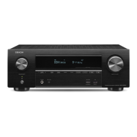
Proceeding : TOP COVER → WiFi ANT → DIGITAL PCB → VIDEO PCB
(1) Remove the connector.
4. VIDEO PCB
N5000
CN5003
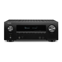
Proceeding : TOP COVER → WiFi ANT → DIGITAL PCB → VIDEO PCB → MAIN PCB
(1) Remove the screws.
(2) Remove the screws. Remove the connector.
Proceeding : TOP COVER → SMPS PCB
See "EXPLODED VIEW" for instructions on removing the SMPS PCB.
Proceeding : TOP COVER → COVER → DIGITAL PCB → TRANS
See "EXPLODED VIEW" for instructions on removing the transformer (TRANS).
5. MAIN PCB
View from the bottom
x3
↑Shooting direction: A↑
x8
x2
CP401
CP401
CP402
CP403
CP405
CP501
6. SMPS PCB
7. TRANS
Before Servicing
This Unit
Electrical Mechanical Repair Information Updating
74
 Loading...