Do you have a question about the Denon DHT-S216 and is the answer not in the manual?
Key safety checks and warnings for technicians during servicing.
Guidelines for preventing electrostatic discharge during handling.
Instructions for accessing and searching the online parts list.
Information on serial number organization and SKU codes.
Steps to ensure proper initialization after service procedures.
Detailed circuit diagrams for various sections of the unit.
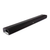
Visual layout of the main PCBs and their assemblies.
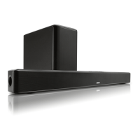
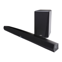
Overview of the system's major components and their interactions.
Power supply block diagram for normal operation.
Power supply block diagram for STB mode.
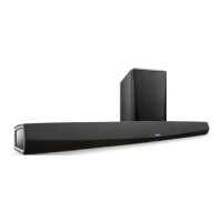
Visual representation of interconnections between main components.
Step-by-step guide for disassembling the unit.
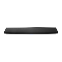
Illustrated breakdown of unit parts for identification.
Diagram showing air leak prevention gasket placement.
Illustration of how the unit is packaged for shipping.
Common issues and their solutions for troubleshooting.
Procedures for entering special modes for diagnostics or settings.
Meaning of LED indications during various operations and modes.
Steps for updating the unit's firmware via USB.
| Audio decoders | DTS, DTS:X, Dolby Digital |
|---|---|
| RMS rated power | - W |
| Audio output channels | 2.0 channels |
| Surround modes quantity | 3 |
| Audio Return Channel (ARC) | - |
| Tweeter diameter | 25.4 mm |
| Tweeter diameter (imperial) | 1 \ |
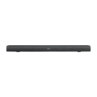
| Product color | Black |
| Wall mountable | Yes |
| Built-in display | No |
| Audio (L/R) in | 1 |
| Connectivity technology | Wired & Wireless |
| Power consumption (standby) | 0.3 W |
| Depth | 120 mm |
|---|---|
| Width | 890 mm |
| Height | 60 mm |
| Soundbar weight | 3400 g |