Do you have a question about the Denon PMA-535R and is the answer not in the manual?
Procedure to check for electrical safety before returning the unit to the customer.
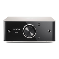
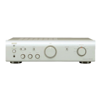
Technical details and performance parameters for the PMA-535R model.
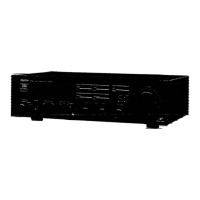
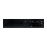
Technical details and performance parameters for the PMA-735R model.
Steps to remove the top cover and front panel of the PMA-535R unit.
Steps to disassemble the inner panel and detach the main P.W.B. and heat sink.
Steps to remove the top cover and front panel of the PMA-735R unit.
Steps to disassemble the inner panel and detach the main P.W.B. and heat sink.
Diagram illustrating signal paths and voltage levels within the amplifier.
Procedure for adjusting the idling current of the amplifier.
Details on the pin assignments and functions of the TMP87C846N integrated circuit.
Diagrams and pinouts for various ICs used in the unit.
Identification and pinouts for transistors, diodes, and LEDs.
Information on the posistor component used in the unit.
Printed wiring board layout for the PMA-535R model.
Printed wiring board layout for the PMA-735R model.
Printed wiring board layout for common sections of both models.
Explanations for markings, symbols, and component specifications in parts lists.
Mapping of unit models to their main P.W.B. part numbers.
Component list for the PMA-535R main P.W.B.
List of capacitors and other components for PMA-535R/735R.
List of semiconductors and resistors for PMA-535R/735R.
List of capacitors and other components for PMA-535R/735R.
Component list for the PMA-735R main P.W.B.
List of capacitors and other components for PMA-535R/735R.
List of P.W.B. units, main chassis, and related hardware for PMA-535R.
List of screws, AC cords, and packing accessories for PMA-535R.
Visual representation of the PMA-535R unit with numbered components.
Visual representation of the PMA-735R unit with numbered components.
List of P.W.B. units, main chassis, and related hardware for PMA-735R.
List of screws, AC cords, and packing accessories for PMA-735R.
Diagram illustrating the wiring between different units of the amplifier.
Schematic of the main unit's electronic circuit for PMA-535R.
Schematics for various sub-units like F. SW, H/P, SP. SW, LED, LOUD, TONE.
Critical information regarding capacitance values, parts changes, and safety checks.
Schematic of the main unit's electronic circuit for PMA-735R.
Schematics for various sub-units of the PMA-735R amplifier.
Critical information regarding capacitance values, parts changes, and safety checks.