Do you have a question about the Denon PMA-360 and is the answer not in the manual?
Provides essential safety guidelines for operating the appliance safely and avoiding hazards.
Details critical installation requirements and warnings to ensure safe setup and operation.
Offers important advice on proper usage, environmental considerations, and maintenance to prevent damage.
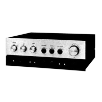
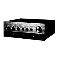
Identifies and illustrates the front and back panel components and connection ports.
Explains how to connect external audio equipment and speaker systems to the amplifier.
Details the purpose and operation of each control on the front and rear panels of the amplifier.
Provides detailed technical specifications for power output, sensitivity, impedance, and other performance metrics.
Illustrates the internal signal flow and electrical levels within the amplifier circuitry.
Outlines the procedure for adjusting critical parameters like idling current for optimal performance.
Step-by-step guide for disassembling the unit to access internal components for servicing.
Lists and identifies the semiconductor devices used in the amplifier's circuitry.
Shows the layout and component placement on the printed wiring boards for reference.
Illustrates the internal wiring connections between different circuit boards and components.
Comprehensive list of parts for the main unit, including part numbers and descriptions.
Detailed parts lists for various control unit versions, specifying part numbers.
Visual representation of the unit's assembly, showing the relationship between parts.
Lists items included in the packaging, such as manuals and accessories, not shown in the exploded view.
Details part number variations across different regional models and revisions.
The complete circuit diagram showing all electronic components and their interconnections.
| Total Harmonic Distortion (THD) | 0.05% |
|---|---|
| Input Sensitivity | 2.5mV (MM), 150mV (line) |
| Signal to noise ratio | 107dB (line) |
| Dimensions | 434 x 112 x 244 mm |
| Speaker load impedance | 4Ω to 16Ω |