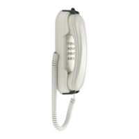
Copyright © 2024 Depaepe NC Page 13 of 15
5) Present the bottom of the device by aligning the 2 holes n°12 (page 4) facing the screws.
6) Slide the post down to lock it.
7) For the anti-theft function, insert the third screw into the anti-theft hole n°2 (page 4).
Screw tightly and plug the hole using the foam plug provided.
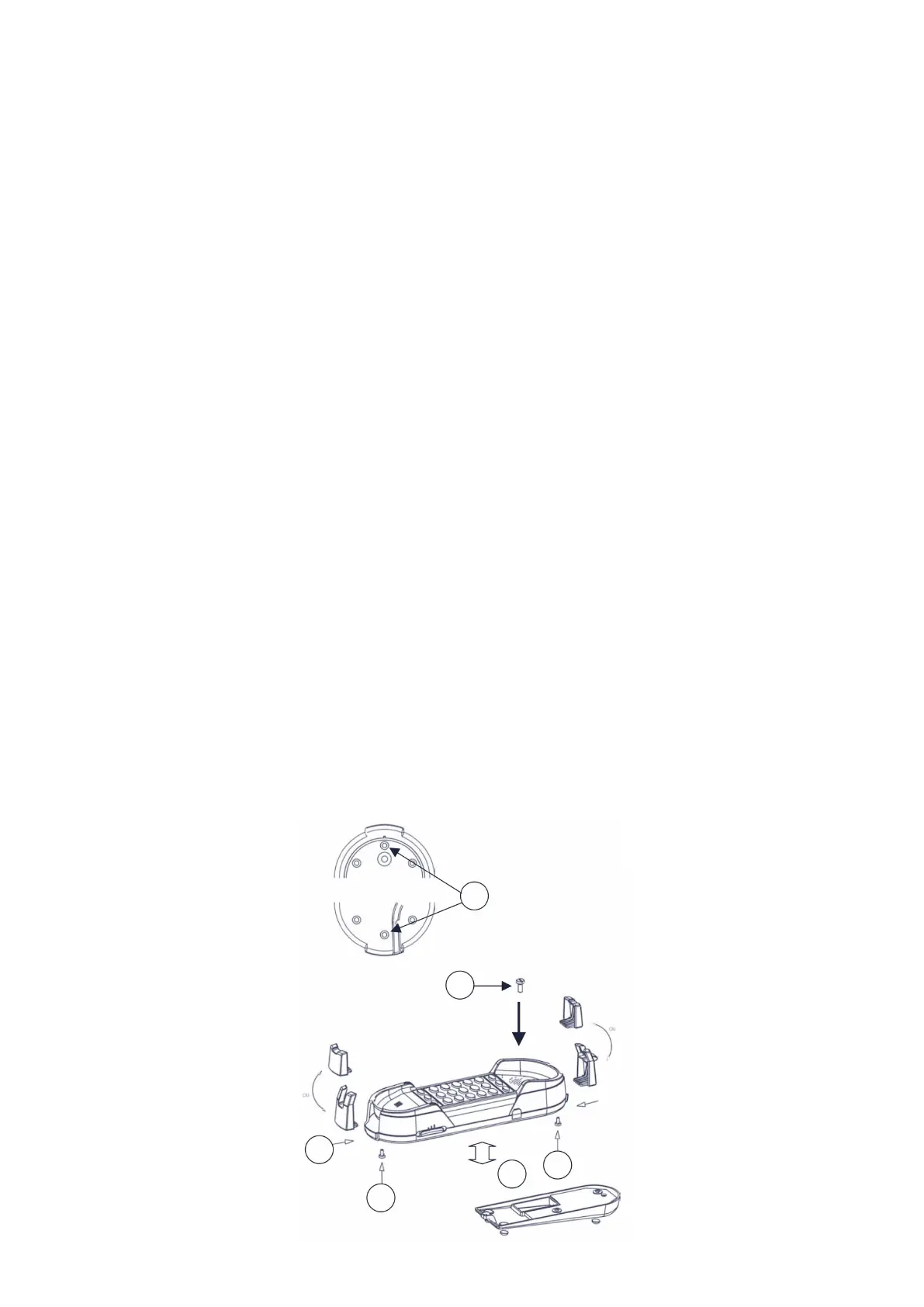
12.3. Installation kit mobile (optionnel) / Mobile kit installation (optional)
Le HD2000 peut être équipé du kit mobile (vendu en option).
Ce kit comprend 1 vis, un socle lesté, un jeu de crochets, et les pieds anti-dérapants.
Voir schéma page suivante :
1) Dévisser les 2 vis (n°1) des crochets noirs situés aux extrémités du téléphone.
2) Insérer les crochets noirs fournis dans leurs emplacements (n°2) et revissez les vis.
3) Brancher le cordon combiné et l’insérer dans le conduit de passage n°14 (page 4).
4) Coller les pieds anti-dérapants sur le socle lesté et l’insérer à l’arrière du téléphone (n°3).
5) Placer la vis fournie avec le kit dans le logement de la vis anti-vol et la visser (n°4).
6) Brancher le cordon de la ligne téléphonique dans le connecteur situé à l’arrière du poste et
l’insérer dans le conduit de passage du socle lesté.
The HD2000 can be equipped with the mobile kit (sold as an option).
This kit includes 1 screw, a weighted base, a set of hooks, and non-slip feet.
See diagram on next page:
1) Unscrew the 2 screws (n°1) from the black hooks located at the ends of the phone.
2) Insert the black hooks provided in their locations (n°2) and tighten the fixing screws.
3) Plug in the combined cord and insert it into passage conduit no. 14 (page 4).
4) Stick the anti-slip feet on the weighted base and insert it into the back of the phone (n°3).
5) Place the screw supplied with the kit in the anti-theft screw housing and screw it in (n°4).
6) Plug the telephone line cord into the connector located on the back of the station and insert it into
the passage conduit of the weighted base.