www.desatech.com
121512-01C4
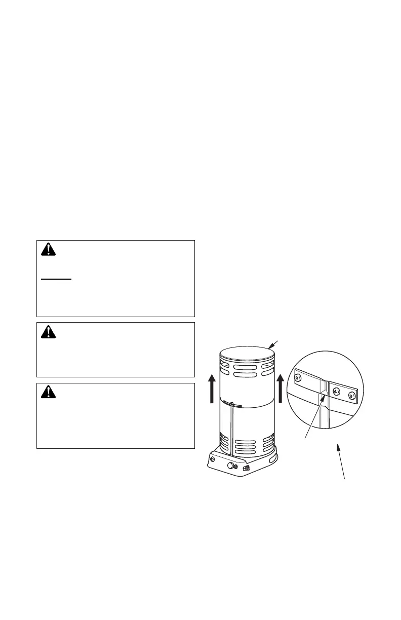
Figure 2 - Lifting Outer Shell
(200,000 Btu/Hr Model Shown)
1 Screw
per Clip
Outer
Shell
Clip in Slot
of Lower
Shell
PROPANE SUPPLY
You must provide propane gas and propane
tank(s).
Use this heater only with a propane vapor
withdrawal supply system. See Chapter 5
of the Standard for Storage and Handling of
Liqueed Petroleum Gas, ANSI/NFPA 58 and/
or CAN/CGA B149.2. Your local l brary or re
department will have this booklet.
This heater will operate with a 20 lb (9.07 kg)
propane tank. However, you can only oper-
ate it in the LOW position during mildly cool
weather for a very short time. At higher heat
settings or during colder weather, you must
use larger tanks.
The amount of propane gas ready for use from
propane tanks varies. Two factors decide this
amount.
1. The amount of propane gas in tank(s)
2. The temperature of tank(s)
The chart below shows the minimum num-
ber of 100 b (45 kg) tanks needed to run
the heater. Connect tanks together with a
manifold.
Average Temperature Number
At Tank Location Of Tanks
(80,000 Btu/Hr models)
20° F (-6.7° C) to 60° F (15.6° C) 1
0° F (-17.8° C) to 20° F (-6.7° C) 2
(200,000 Btu/Hr models)
20° F (-6.7° C) to 60° F (15.6° C) 2
0° F (-17.8° C) to 20° F (-6.7° C) 3
Less gas is vaporized at lower temperatures.
Your local propane gas dealer will help you
select the proper supply system.
INSTALLATION
WARNING: Review and un-
derstand the warnings in the
Safety section, page 2. They are
needed to safely operate this
heater. Follow all local codes
when using this heater.
CAUTION: Never ignite and/
or run this heater unless the
shells are fully extended and
locked into position.
CAUTION: Not intended
for use on nished oors. This
includes, but is not limited to
carpet, rugs, vinyl, treated and
synthetic wood ooring.
Tools Required:
• 7/8" wrench
• 3/4" wrench (or adjustable wrench)
• #1 Phillips screwdriver
OUTER SHELL
IMPORTANT: When the heater is rst re-
moved from carton, the outer shell is in the
down position. Protect hands before lifting
outer shell. Never grasp bare metal without
hand protection.
1. Care must be taken to protect hands dur-
ing this step. Lift outer shell straight up
as shown in Figure 2, until all three clips
engage slots in lower shell. Screw holes
will line up at this point.
2. Lock clips into place with 1 screw each as
shown in Figure 2. The heater must not be
operated unless the outer shell is properly
extended and fully locked into place.