EasyManua.ls Logo

Desmi NSL 100-265 User Manual

Default Icon
151 pages
To Next Page IconTo Next Page
Page #1 background imageLoading...
Page #1 background image
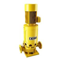
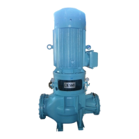
DESMI Vertical In-Line Centrifugal Pump
OPERATION AND MAINTENANCE INSTRUCTIONS
NSL MONOBLOC & SPACER
DESMI Pumping Technology A/S
Tagholm l, DK-9400 Nørresundby, Denmark
Tel.: +45 96 32 81 11
Fax: +45 98 17 54 99
E-mail: desmi@desmi.com
Internet: www.desmi.com
Manual:
T1542
Language:
English
Revision:
A.1
Special pump Number. ...............................................
Original instructions

Table of Contents

Questions and Answers:

Desmi NSL 100-265 Specifications

General IconGeneral
Pump TypeSelf-priming centrifugal pump
MaterialCast iron
Impeller MaterialBronze
Seal TypeMechanical seal
Inlet Diameter100 mm
Outlet Diameter100 mm

Summary

SAFETY

2.1.1. Signal words

Explanation of DANGER, WARNING, and CAUTION signal words.

2.1.2. Hazard symbols

Symbols indicating general hazard, electrical hazard, explosion protection.

2.2. Intended use

Pump must be operated within limits and for specified fluids.

2.3. Consequences and risks caused by non-compliance with this manual

Non-compliance leads to warranty forfeiture and risks like explosion or injury.

2.5. Safety information for the operator/user

Operator must fit guards, use PPE, contain leakages, and eliminate electrical hazards.

2.6. Safety information for maintenance, inspection and installation

Modifications require consent. Use original parts. Work by authorized personnel.

2.7. Unauthorised modes of operation

Never operate pump outside documented limits. Warranty void if used incorrectly.

2.8.1. Marking

Details on EX marking for NSL pumps and motor marking.

2.8.2. Temperature limits

Max. allowed liquid temperature is 80°C for fresh water. Contact DESMI for higher temps.

2.8.3. Monitoring equipment

Operate within limits. Use monitoring devices if compliance cannot be warranted.

2.8.4. Operating limits

Refer to chapter 1.4 for liquid temperatures. PT100 sensor recommended for high temps.

TRANSPORTATION, PREVENTATION AND TEMPORARY STORAGE

3.2. Transport

Safety precautions for transport, including falling object hazard and risk of damaging shaft seal.

TECHNICAL SPECIFICATION

4.1. Work range

Working range depends on design, connection, and sealings. Includes media and ambient temp. ranges.

INSTALLATION

5.1. Mounting / Fastening

Instructions for mounting and fastening the pump on a solid foundation.

5.2. Wiring

Special skills required for wiring. Obey valid rules and regulations.

Maximum suction up height (suction lift)

Formula and explanation for calculating maximum suction up height to avoid cavitation.

COMMISSIONING, START-UP AND SHUTDOWN

6.1. Prerequisites for commissioning / start-up

Conditions to meet before starting up: proper connection, priming, venting, rotation check.

6.2. Priming and venting the pump

Explosion hazard warning for incorrect start-up. Vent and prime pump before starting.

Venting and priming

Automatic priming system prevents dry running. Two types: priming pump and priming air ejector.

6.3. Start up

Explosion hazard warnings for leakage and damage. Start up with discharge valve slightly open.

6.3.1. Start-up procedure

Steps before starting: check shaft rotation, liquid fill. Start pump momentarily to check rotation.

6.4. Checking the shaft seal

Mechanical seal only leaks slightly. Seals are maintenance-free.

6.5. Shut down

Procedure for shutting down pump, including cooling down hot surfaces and stopping motor.

6.6. Operating limits

Comply with working range in chapter 4.1 and technical data in chapter 4.2.

6.7. Frequency of starts

Explosion hazard/damage to motor warning. Frequency depends on motor temperature increase.

6.10. Return to service

Observe commissioning/start-up sections. Perform servicing before returning to service.

TROUBLESHOOTING

7.1. Mechanical seal failure analysis

Analysis of pump settling, leakage, NPSH issues, and how to avoid them.

INSPECTION AND SERVICE PLAN

8.1. Supervision of operation

Explosion hazard, leakage, fire hazard warnings. Monitor operation, check seals, bearings.

Inspection and maintenance intervals for normal applications

Table detailing daily, weekly, monthly, and long-term inspection/maintenance tasks.

8.2.1. Cleaning filter

Risk of property damage due to clogged filter. Monitor contamination and clean filter.

8.2.2. Drainage and cleaning

Environmental hazard warning for hot fluids. Drain, flush, clean pump before transport.

DISMANTLING THE PUMP SET

9.1.1. Access to impeller

Steps to access the impeller for Ø215/265-02 and Ø215/265-12 combinations.

9.1.2. Dismantling shaft seal

Steps for dismantling the shaft seal for Ø215/265-02 and Ø215/265-12 combinations.

9.1.5. Inspection

Check parts for wear and damage: sealing ring, shaft seal seat, rubber parts, bearings.

9.2.1. Access to impeller

Steps to access the impeller for Ø215/265 and Ø330/415/418/465/525 combinations.

ASSEMBLING THE PUMP SET

10.1.2. Fitting shaft seal

Steps to clean recess, lubricate seat, and press seat into place.

10.1.3. Fitting impeller

Mount pump shaft on motor shaft, check run-out. Mount motor bracket and shaft seal for Ø215/265.

10.2.4. Fitting shaft seal

Clean recess, lubricate seat, and press seat into place for pumps with balanced shaft seal.

10.2.5. Fitting impeller

Fit sunk key, lead impeller towards shaft shoulder, secure with washers and nut/set screw.

Related product manuals