6
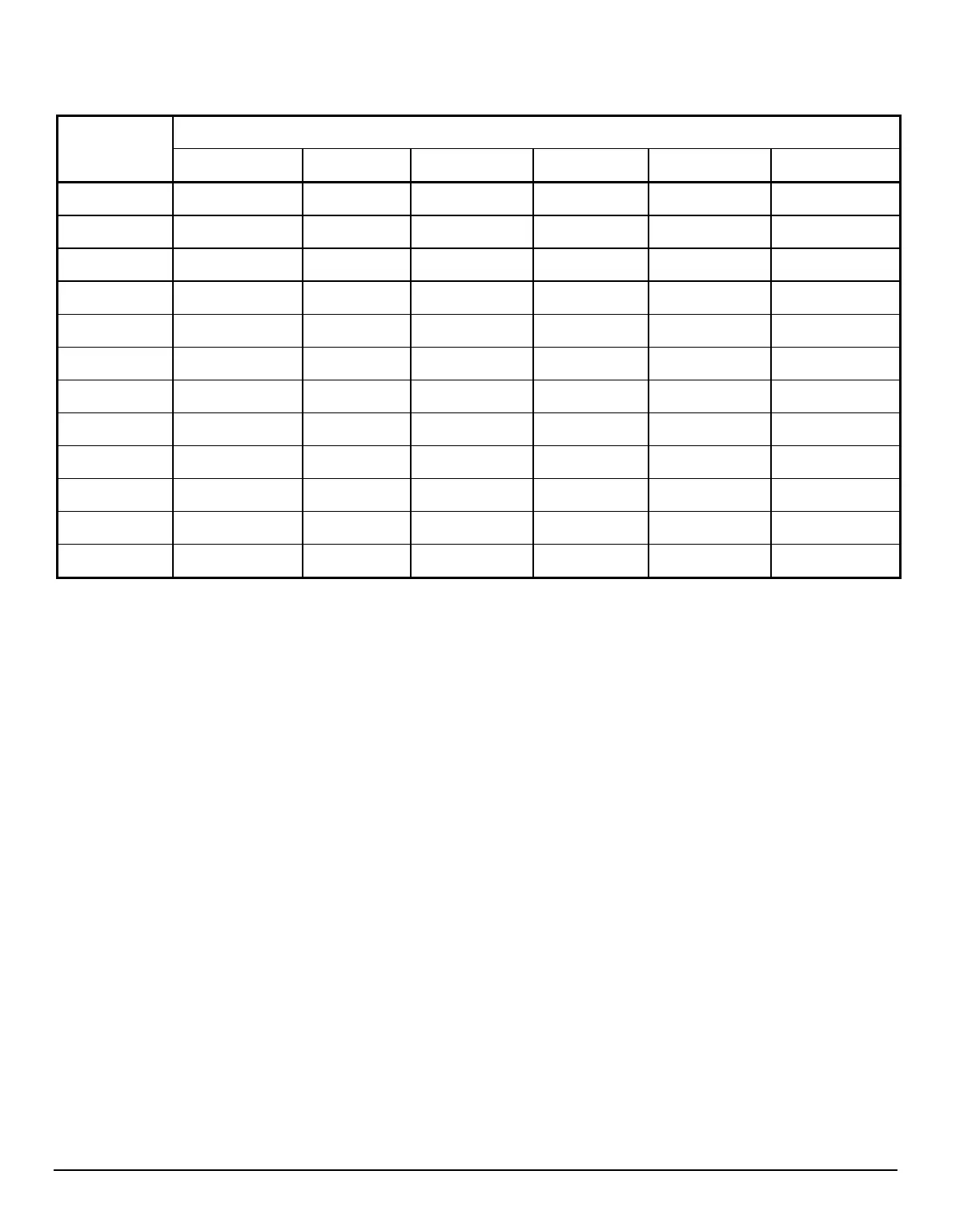
TABLE 1
Suggested gas piping dimensions
Model Distance from the unit gas regulator, in equivalent feet, for a pressure loss of less than 0.5" W.C.
0-25 25-50 50-100 100-200 200-300 300-500
HGC-0404 1 ¼" 1 ¼" 1 ½" 2" 2" 2"
HGC-0505 1 ¼" 1 ¼" 1 ½" 2" 2" 2"
HGC-0606 1 ¼" 1 ½" 2" 2" 2" 2 ½"
HGC-0707 1 ½" 1 ½" 2" 2" 2 ½" 2 ½"
HGC-0808 1 ½" 1 ½" 2" 2" 2 ½" 2 ½"
HGC-0909 1 ½" 2" 2" 2 ½" 2 ½" 3"
HGC-1010 1 ½" 2" 2" 2 ½" 2 ½" 3"
HGC-1111 2" 2" 2 ½" 2 ½" 3" 3"
HGC-1212 2" 2" 2 ½" 2 ½" 3" 3"
HGC-1313 2" 2" 2 ½" 3" 3" 3"
HGC-1414 2" 2" 2 ½" 3" 3" 3"
HGC-1515 2" 2" 2 ½" 3" 3" 4"
The front of the control panel is equipped with indicator
lights. The function of each light (from left to right) is as
follows:
a. L1 : GREEN - Call for heat on the unit. A call for
heat is defined by continuity between terminals “1”
and “2”.
b. L2 : RED - Lack of water circulation in the heat
exchanger. The flow switch contact is open.
c. L3 : RED - The water temperature in the heat
exchanger is too high. The High Limit Control
contact is open.
d. L4 : RED - No flame. There is no voltage between
the main gas valve terminals, even if there is a call
for heat (L1 on).
e. L5 : GREEN - The main gas valve is operating
(low or high fire).
f. L6 : GREEN - The main gas valve is operating on
the second stage (high fire).
8) WATER PIPING
8.1) Overview
A pressure regulator must be installed on the water feed
line to the unit and adjusted to a pressure lower than the
unit safety valve setting. The system must be equipped
with a circulating pump, expansion tank, air vents and
maintenance valves as indicated in Figures 3.3 to 3.6
(depending on the system). The installation of a by-pass
between the return and supply pipes is good plumbing
practice and ensures a good return temperature in the
heat exchanger.
8.2) Variable volume water system:
Heating systems incorporating zone valves, zone
circulators or 3-way mixing valves, operate with reduced
water circulation through the unit. Therefore, the
installation must be planned for a minimum required
circulation of water through the unit. A water flow lower
than the minimum threshold could result in a significant
water temperature elevation and provoke knocking
noises, vibration and short cycling. All these conditions
are unstable and damaging to the appliance. Size your
circulating pump so that there will always be a minimum
flow of water through the unit, as recommended in
Table 3. If short cycling persists, the use of the second
stage of the main gas valve (2-stage gas valve is
standard equipment) should be considered.