6
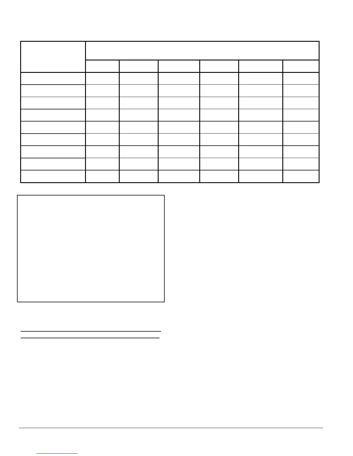
TABLE 1
Recommended gas piping dimensions
Distance from the unit gas regulator, in equivalent feet, for a pressure loss of less than
0.5" W.C.
Model
0-25 25-50 50-100 100-200 200-300 300-500
HGRC068
½" ½" ¾" 1" 1" 1"
HGRC105
¾" ¾" 1" 1" 1 ¼" 1 ¼"
HGRC136
¾" 1" 1" 1 ¼" 1 ¼" 1 ¼"
HGRC170
1" 1" 1 ¼" 1 ¼" 1 ¼" 1 ½"
HGRC204
1" 1" 1 ¼" 1 ¼" 1 ¼" 1 ½"
HGRC238
1" 1 ¼" 1 ¼" 1 ¼" 1 ½" 1 ½"
HGRC272
1" 1 ¼" 1 ¼" 1 ½" 1 ½" 2"
HGRC306
1" 1 ¼" 1 ¼" 1 ½" 1 ½" 2"
HGRC340
1 ¼" 1 ¼" 1 ¼" 1 ½" 2" 2"
CAUTION
The unit must be completely isolated from
corrosive chemical vapours and excessively
moist air. FAILURE TO COMPLY WITH THIS
CONDITION CAN RENDER YOUR
WARRANTY NULL AND VOID. When a
mechanical air supply device is used, the
installer must make certain that no air
movement is created around the unit.
Furthermore, this mechanical device (fan,
damper, etc.) must be electrically connected to
the unit to lockout the latter in case of device
failure.
7) ELECTRICAL WIRING
All wiring must be in accordance with local authorities
and the “Canadian Electrical Code - CSA C22.1/ Part I”.
The unit must be connected to a 15 amp protected
circuit with a single phase voltage of 120 VAC at 60 Hz.
The installer must wire the unit according to the
appropriate electrical diagram. If a motorized damper is
used, the wire harness provided with the unit must be
used without modification for this connection.
Consult the following figures for the appropriate
electrical diagrams:
Figure 4.1: Constantly burning pilot
Figure 4.2: Constantly burning pilot with motorized
damper
Figure 4.3: Intermittent pilot (electronic),
White-Rodgers
Figure 4.4: Intermittent pilot (electronic), Honeywell
Figure 4.5: Intermittent pilot (electronic), Honeywell
and motorized damper
Figure 4.6: Intermittent pilot (hot surface)
Figure 4.7: Intermittent pilot (hot surface) with
motorized damper
Figure 4.8: Constantly burning pilot with side wall
venting
Figure 4.9: Constantly burning pilot with side wall
venting and motorized damper
Figure 4.10: Intermittent pilot (electronic)
White-Rodgers with side wall venting
Figure 4.11: Intermittent pilot (electronic) Honeywell
with side wall venting
Figure 4.12: Intermittent pilot (electronic) Honeywell
with motorized damper and side wall
venting
Figure 4.13: Intermittent pilot (hot surface) with side
wall venting
Figure 4.14: Intermittent pilot (hot surface) with
motorized damper and side wall venting