8
The chimney must have sufficient draft to ensure the
normal and safe operation of the appliance. Consult the
CAN/CGA B149 Installation Code. Also, the installation
must conform to all regulations of the authorities having
jurisdiction.
10.2) Through the wall venting
All HGRC units are approved for installation with
through the wall venting packages. Please consult
Table 2 for correct package selection and refer to the
wiring diagrams related to side wall venting.
Note : Please refer to the Instruction Manual supplied
with your side wall venting package.
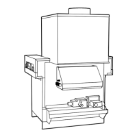
10.3) Motorized vent damper (when used)
The HGRC unit can be equipped with a motorized
damper device that closes the vent pipe when the main
burners are off. This damper is factory installed and
wired and must not be modified or relocated.
CAUTION
The draft hood and the motorized damper
must be installed without any modification.
The venting system shall be arranged such a way that
the automatic vent damper device can serve only the
appliance for which it was supplied HGRC.
The orientation of the damper in the venting system
shall be such that the arrow on the body of the damper
is in the direction of the flow of the combustion gases.
Also, the damper actuator is equipped with a coupling
which is arrow shaped. When the damper is open, this
arrow points in the direction of the gas flow and when
the damper is closed, it is perpendicular to the gas flow.
These indicators (arrows) shall be in a visible location
following installation.
CAUTION
The damper must be in the “Open” position
when the appliance main burners are
operating.
It may be necessary to manually operate the damper if
the main burners have to be operated during a damper
actuator breakdown.
CAUTION
It is dangerous and not permitted to modify the
unit wiring to allow "damperless" burner
operation if the motorized damper is still in
place.
To manually open the damper, please follow these
steps:
1.
Remove the vent damper junction box cover;
2. Place the selection switch in the "SERVICE"
position;
3. Using a screwdriver, turn the manual adjustment
screw counter-clockwise until the arrow points in the
direction of the gas flow;
4. To close the damper, continue rotating the screw in
the counter-clockwise direction.
CAUTION
To ensure normal damper operation, put the
switch back in the "NORMAL" position.