Deutronicstr. 5, D - 84166 Adlkofen
Tel.: +49 (0) 8707 920-199
Fax: +49 (0) 8707 1004
E-Mail: sales@deutronic.com
http://www.deutronic.com
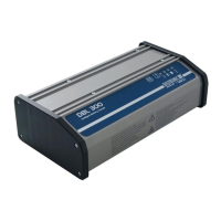
2) Technical Data
Type Input Voltage Output Voltage Output Current
DBL300-14 100-240VAC 14,4/13,2VDC 20A *
DBL300-28 100-240VAC 28,8/26,4VDC DBL300-28
DBL500-14 100-240VAC 14,4/13,2VDC 36A *
DBL500-28 100-240VAC 28,8/26,4VDC
DBL700-14 100-240VAC 14,4/13,2VDC 45A *
DBL700-28 100-240VAC 28,8/26,4VDC
DBLW1200-14 100-240VAC 14,4/13,2VDC 60A / 80A *
DBLW1200-28 100-240VAC 28,8/26,4VDC
*) Current limit description:
Current limiting is performance related and temperature dependent
28VDC DBL variant:
Charging mode with auto select circuit for 12VDC or 24VDC lead batteries (detects and supplies both battery types), 'Power Supply
Mode' ONLY for 24VDC on-board electrical systems!
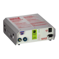
3) Control Elements
Afterwards the control elements of the DBL300 / DBL500 / DBL700 / DBLW1200 are given (incl. LEDs and push-button):
[1]
Error (red LED)
[4]
Battery empty (yellow LED)
[2]
End of charging process / trickle charge (green LED)
[5]
MODE push-button to select operation mode
Note: Operation mode can only be changed after the
STOP button has been pressed
[3]
Battery half full (yellow LED)
[6]
START / STOP push-button