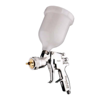
Flushing the system:
1. Turn off atomising air ‘B’ and coating material ‘C’ supplies and relieve pressures.
CAUTION: DO NOT turn off diaphragm air supply ‘A’.
2. Replace coating material with a suitable solvent, reduce pressure and turn on supply.
3. Remove air cap, operate the gun with diaphragm control valve, do not turn on atomising air supply. Flush system until
clean.
Clean air cap by immersing in solvent, brush or wipe clean. If any holes in the air cap are blocked use a toothpick or broom
straw to remove the obstruction. Never use a steel wire or hard implement which will damage the air cap and result in a
distorted pattern
Note: Order numbers shown in parts list for figure 1 with suffix ‘-K5’ etc. at the end of the order No. indicates a kit of parts.
Example JGD-14-K5 is a kit of five seals.
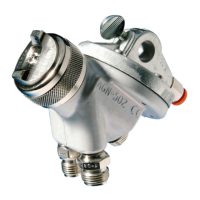
Caution: Always ensure that the fan air control valve is in the fully open position by turning the screw (13) ounter-clockwise
before fitting the valve assembly to the gun body and when removing the nozzle and baffle.
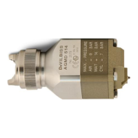
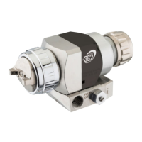
NOZZLE (2) AND BAFFLE (3).
Turn screw (13) counter-clockwise. Remove parts in the following order (1, 2, 3 and 4). Replace any worn or damaged parts.
Reassemble in reverse order.
Recommended tightening torque for nozzle (2), 25-27 Nm (221 - 239 lbf in).
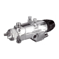
SEAT (5) or DIAPHRAGM (6).
Remove screws (9), top plate and diaphragm (6). Unscrew seat (5) using a
1
/4" hexagon key. Replace worn or damaged parts.
Reassemble in reverse order. Recommended tightening torque for screws (9), 4 Nm (35 lbf in).
Note: Protective diaphragm AGN-8 (see accessories) is fitted between the gun body and the rubber diaphragm (6) to prevent
solvent based coating material contacting the rubber diaphragm.
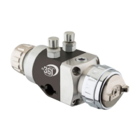
‘O’ RING (12).
Turn screw (13) counter-clockwise and unscrew valve body (11). Remove parts (10,13 and 12). Replace ‘0’ ring (12) and
reassemble in reverse order. Turn screw (13) counter-clockwise before fitting valve assembly to gun body.
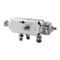
CONNECTORS (14, 15).
Remove connector (14 or 15) and clean threads in gun body. Apply a medium strength thread locking/seal ing compound to
the taper thread of the new connector, screw into gun body and tighten. Recommended torque 16 Nm (140 lbf in).
Service kit Order KK-4998 contains parts marked with * in Parts List for figure 1.
Protective diaphragm Order AGN-8-K5. Converts gun for use with solvent based materials. Fit between the gun body and
standard rubber diaphragm.
Multipurpose spanner Order SPN-5. Contains necessary sizes for maintenance and hose connections.
Cleaning brush Order 4900-5-1-K3 for cleaning threads and recesses of gun.
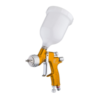
Remote pressure Cup: maximum working pressure 2 bar (30 lbf/in
2
), capacity 2.0 litres. Add thread code to order No.,
B=BSP, N=NPS. Order hoses separately.
KB-522: NOT SUITABLE FOR USE WITH HYDROGENATED HYDROCARBON SOLVENTS OR WATERBOURNE
MATERIALS.
KB-522-SS: IS SUITABLE FOR USE WITH HYDROGENATED HYDROCARBON SOLVENTS OR WATERBOURNE
MATERIALS.
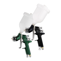
Pressure feed tanks: A range of sizes are available manufactured in zinc coated steel or stainless steel construction. Please
contact your local DEVILBISS Distributor for information.
ACCESSORIES
REPLACEMENT OF PARTS
PREVENTATIVE MAINTENANCE
6 © ITW LTD 1994 – SB-E-2-660