4
2
5
6
8
3
7
1
9
10
11
12
13
15
16
17
14
11
15
16
17
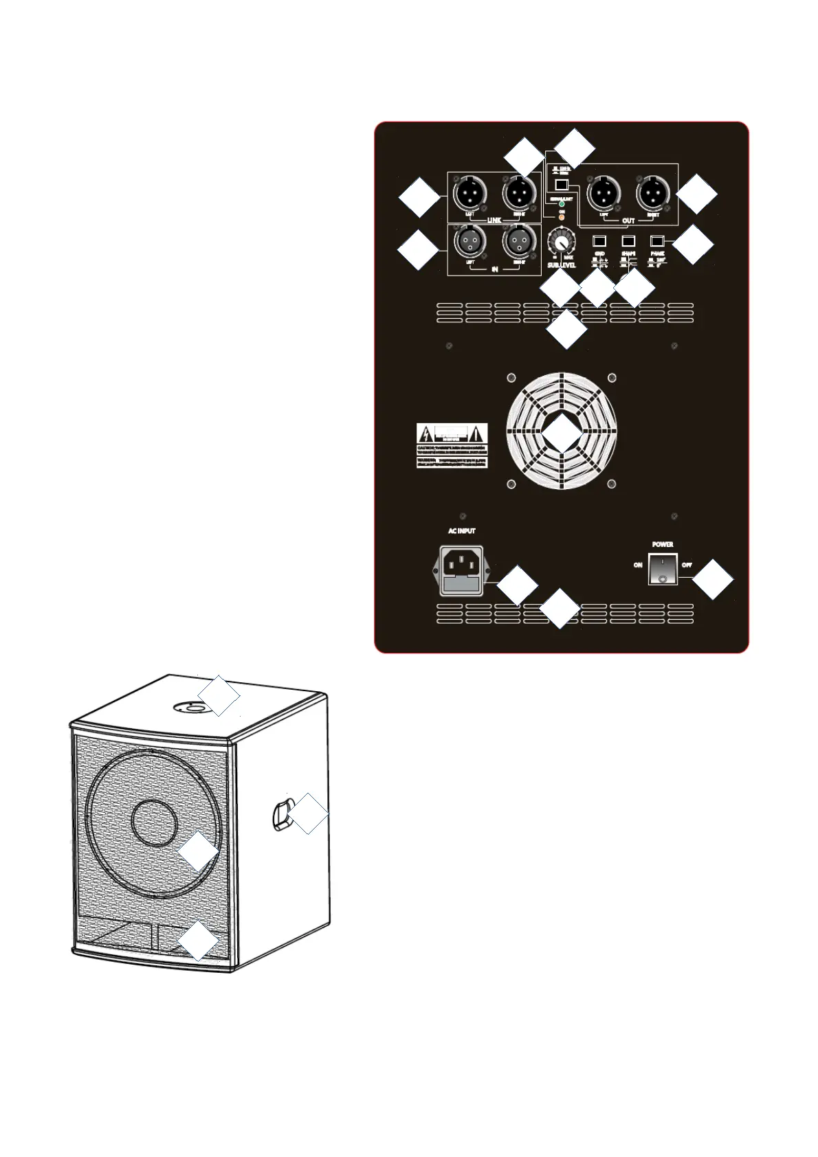
Guidelines and operation of this device
These images apply to all models.
1. link outputs (copy of input signal) via
balanced 3-pin XLR
2. inputs via balanced 3-pin XLR
3. subwoofer volume control
4. ground lift, interrupts the ground loop of
the audio inputs to eliminate interference
5. boost filter, boosts frequencies around 45 Hz
when switched on
6. phase inverter (180 degrees)
7. filtered outputs via balanced 3-pin
XLR + low cut, cuts off frequencies lower than
80 or 120 Hz
8. clip limiter LED
9. signal indicator LED
10. fan
11. ventilation slots
12. on/off switch
13. IEC C14 power input with fuse holder
14. handle
15. M20 screw thread for mounting a distance
pole
16. low tone speaker
17. bass reflex ports
The information in this user manual is subject to change at any time without notice.
Version: 1.0 Date of creation and author's initials: 23-09-2017 RV Revision date and author's initials: -