7
ENGLISH
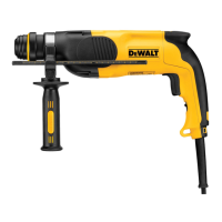
Side Handle (Fig.A, B)
WARNING: To reduce the risk of personal injury, ALWAYS
operate the tool with the side handle properly installed.
Failure to do so may result in the side handle slipping
during tool operation and subsequent loss of control. Hold
tool with both hands to maximizecontrol.
The side handle2 clamps to the front of the gear case and may
be rotated 360˚ to permit right- or left-hand use.
Mounting the Straight Side Handle (Fig. B)
1. Widen the ring opening of the side handle
2
by rotating it
anti-clockwise.
2. Slide the assembly onto the nose of the tool, through the
steel ring
14
and onto the collar
3
, past the chisel holder
andsleeve.
3. Rotate the side handle assembly to the desired position. For
hammerdrilling horizontally with a heavy drill bit, place the
side handle assembly at an angle of approximately 20° to
the tool for optimumcontrol.
4. Lock the side handle mounting assembly in place by
securely tightening the handle
2
rotating it clockwise so
that the assembly will notrotate.
Bit and Bit Holder
WARNING: Burn Hazard. ALWAYS wear gloves when
changing bits. Accessible metal parts on the tool and bits
may get extremely hot during operation. Small bits of
broken material may damage barehands.
The hammerdrill can be fitted with different bits depending on
the desired application. Use sharp drill bitsonly.
Inserting and Removing SDS MAX
Accessories (Fig. C)
This machine uses SDSMAX bits and chisels (refer to the inset in
FigureC for a cross-section of an SDSMAX bitshank).
1. Clean the bitshank.
2. Pull back the locking sleeve
7
and insert the bitshank.
3. Turn the bit slightly until the sleeve snaps intoposition.
4. Pull on the bit to check if it is properly locked. The
hammering function requires the bit to be able to move
axially several centimetres when locked in the toolholder.
5. To remove a bit pull back the tool holder locking sleeve
7
and pull the bit out of the bit holder
6
.
OPERATION
Instructions for Use
WARNING: Always observe the safety instructions and
applicableregulations.
WARNING: To reduce the risk of serious personal
injury, turn tool off and disconnect tool from power
source before making any adjustments or removing/
installing attachments or accessories. Be sure the
trigger switch is in the OFF position. An accidental start-up
can causeinjury.
Proper Hand Position (Fig. D)
WARNING: To reduce the risk of serious personal injury,
ALWAYS use proper hand position asshown.
WARNING: To reduce the risk of serious personal
injury, ALWAYS hold securely in anticipation of a
suddenreaction.
Proper hand position requires one hand on the main handle5,
with the other hand on the side handle2.
Operation Modes (Fig.A)
WARNING: Do not select the operating mode when the
tool isrunning.
Your tool is equipped with a mode selector switch4 to
selectthe mode appropriate to desiredoperation.
Symbol Mode Application
Rotary
Hammering
Drilling into concrete and
masonry
Hammering
only
Lightchipping
Bit Adjustment
Chisel bit position
adjustment
To Select an Operating Mode
• Rotate the mode selector dial so that the arrow points to the
symbol corresponding with the desiredmode.
NOTE: The mode selector switch4 must be in rotary drilling,
rotary hammering or hammering only mode at all times. There
are no operable positions inbetween. It may be necessary to
briefly run the motor after having changed from 'hammering
only' to 'rotary' modes in order to align thegears.
Indexing the Chisel Position (Fig. A)
The chisel can be indexed and locked into 24 differentpositions.
1. Rotate the mode selector switch
4
until it points towards
the position.
2. Rotate the chisel in the desiredposition.
3. Set the mode selector switch
4
to the “Hammering
Only”position.
4. Twist the chisel until it locks inposition.
Performing an Application (Fig. A)
WARNING: TO REDUCE THE RISK OF PERSONAL
INJURY, ALWAYS ensure workpiece is anchored or
clamped firmly. If drilling thin material, use a wood
“backup” block to prevent damage to thematerial.
WARNING: Always wait until the motor has come to
a complete standstill before changing the direction
ofrotation.
Switching On and Off (Fig. A)
To turn the tool on, depress the trigger switch1.
To stop the tool, release the triggerswitch.

 Loading...