8
ENGLISH
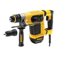
Drilling with a Solid Bit (Fig. A)
1. Insert the appropriate drillbit.
2. Set the mode selector switch
4
to the
hammerdrillingposition.
3. Set the electronic speed and impact control dial
9
.
4. Fit and adjust the side handle
2
.
5. Mark the spot where the hole is to bedrilled.
6. Place the drill bit on the spot and switch on thetool.
7. Always switch off the tool when work is finished and
beforeunplugging.
Drilling with a Core Bit (Fig. A)
1. Insert the appropriate corebit.
2. Assemble the centerdrill into the corebit.
3. Set the mode selector switch
4
to the
hammerdrillingposition.
4. Turn the electronic speed and impact control dial
9
to a
medium or high speedsetting.
5. Fit and adjust the side handle
2
.
6. Place the centerdrill on the spot and switch on the tool. Drill
until the core penetrates into the concrete approximately
1cm.
7. Stop the tool and remove the centerdrill. Place the core bit
back into the hole and continuedrilling.
8. When drilling through a structure thicker than the depth of
the core bit, break away the round cylinder of concrete or
core inside the bit at regularintervals.
To avoid unwanted breaking away of concrete around
the hole, first drill a hole the diameter of the centerdrill
completely through the structure. Then drill the cored hole
halfway from eachside.
9. Always turn the tool off when work is finished and
beforeunplugging.
Chipping and Chiselling (Fig. A)
1. Insert the appropriate chisel and rotate it by hand to lock it
into one of 24positions.
2. Set the mode selector switch
4
to the hammering
onlyposition.
3. Set the electronic speed and impact control dial
9
.
4. Fit and adjust the side handle
2
.
5. Turn the tool on and startworking.
6. Always turn the tool off when work is finished and
beforeunplugging.
MAINTENANCE
Your DeWALT power tool has been designed to operate
over a long period of time with a minimum of maintenance.
Continuous satisfactory operation depends upon proper tool
care and regularcleaning.
WARNING: To reduce the risk of serious personal
injury, turn tool off and disconnect tool from power
source before making any adjustments or removing/
installing attachments or accessories. Be sure the
trigger switch is in the OFF position. An accidental start-up
can causeinjury.
Lubrication
Your power tool requires no additionallubrication.
Cleaning
WARNING: Blow dirt and dust out of the main housing
with dry air as often as dirt is seen collecting in and around
the air vents. Wear approved eye protection and approved
dust mask when performing thisprocedure.
WARNING: Never use solvents or other harsh chemicals
for cleaning the non-metallic parts of the tool. These
chemicals may weaken the materials used in these parts.
Use a cloth dampened only with water and mild soap.
Never let any liquid get inside the tool; never immerse any
part of the tool into aliquid.
Optional Accessories
WARNING: Since accessories, other than those offered
by
DeWALT, have not been tested with this product, use
of such accessories with this tool could be hazardous.
To reduce the risk of injury, only DeWALT recommended
accessories should be used with thisproduct.
Various types of SDSMAX drill bits and chisels are available as
anoption. Accessories and attachments used must be regularly
lubricated around the SDSMAXfitment.
Consult your dealer for further information on the
appropriateaccessories.
Protecting the Environment
Separate collection. Products and batteries marked
with this symbol must not be disposed of with normal
householdwaste.
Products and batteries contain materials that can
be recovered or recycled reducing the demand for raw
materials. Please recycle electrical products and batteries
according to local provisions. Further information is available at
www.2helpU.com.
 Loading...