ENGLISH
10
INTENDED USE
Your
DCCS620 Chainsaw is ideal for pruning
applications and cutting logs up to 10" (254 mm)
indiameter.
DO NOT use under wet conditions or in presence of
flammable liquids orgases.
This chainsaw is a professional powertool. DO NOT let
children come into contact with the tool. Supervision is
required when inexperienced operators use thistool.
ASSEMBLY
Installing the Guide Bar and Saw Chain
(Fig. A, D–F, H)
CAUTION: Sharp chain. Always wear protective
gloves when handling the chain. The chain is sharp
and can cut you when it is notrunning.
WARNING: Sharp moving chain. To prevent
accidental operation, ensure that battery is removed
from the tool before performing the following
operations. Failure to do this could result in serious
personalinjury.
If the saw chain
5
and guide bar
4
are packed separately
in the carton, the chain has to be attached to the bar, and
both must be attached to the body of thetool.
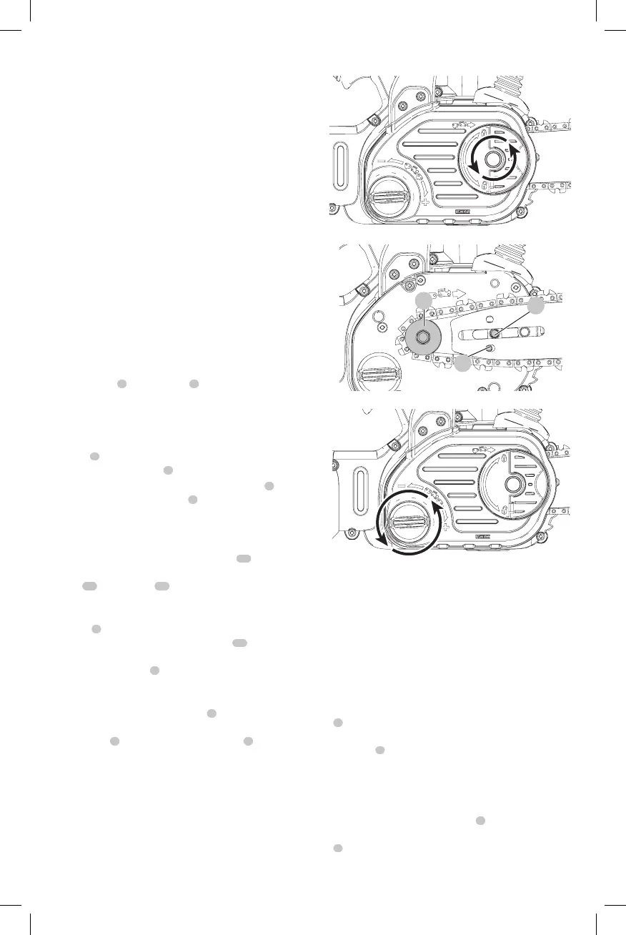
• Place the saw on a flat, firmsurface.
• Flip up locking lever and rotate the bar adjust locking
knob
8
counterclockwise as shown in FigureD to
remove sprocket cover
6
.
• Wearing protective gloves, grasp the saw chain
5
and
wrap it around the guide bar
4
, ensuring the teeth are
facing the correct direction (see FigureH).
• Ensure the chain is properly set in the slot around the
entire guidebar.
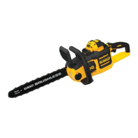
• Place the saw chain around the sprocket
18
. While
lining up the slot on the guide bar with chain tensioning
pin
20
, and the bolt
19
, on the base of the tool as
shown in FigureE.
• Once in place, hold the bar still, replace sprocket
cover
6
. Make sure tool-free tension assembly bolt
hole on the cover lines up with the bolt
19
, in the
main housing. Flip up locking lever and rotate the bar
adjust locking knob
8
clockwise until it clicks, then
loosen knob one full turn, so that the saw chain can be
properlytensioned.
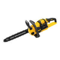
• Rotate the chain tensioning knob
9
clockwise to
increase tension as shown in FigureF. Make sure the
saw chain
5
is snug around the guide bar
4
. Tighten
the bar adjust locking knob until it clicks. The bar is
secure after three audible clicks are heard. Further
tightening is notrequired.
Fig. D
Fig. E
18
19
20
Fig. F
Adjusting Chain Tension (Fig. A, G )
CAUTION: Sharp chain. Always wear protective
gloves when handling the chain. The chain is sharp
and can cut you when it is notrunning.
WARNING: Sharp moving chain. To prevent
accidental operation, ensure that battery is removed
from the tool before performing the following
operations. Failure to do this could result in serious
personalinjury.
• With the saw on a flat, firm surface, check the saw chain
5
tension. The tension is correct when the chain snaps
back after being pulled 1/8" (3mm) away from the
guide bar
4
with light force from the index finger and
thumb as shown in FigureI. There should be no “sag”
between the guide bar and the chain on the underside
as shown in FigureG.
• To adjust saw chain tension, flip up locking tab and
rotate the bar adjust locking knob
8
counterclockwise
one full turn. Rotate the chain tensioning knob
9
clockwise until the chain tension is correct as
instructedabove.