12
ENGLISH
Proper Hand Position (Fig. G)
WARNING: To reduce the risk of serious personal injury,
ALWAYS use proper hand position asshown.
WARNING: To reduce the risk of serious personal
injury, ALWAYS hold securely in anticipation of a
suddenreaction.
OPERATION
Instructions for Use
WARNING: Always observe the safety instructions and
applicableregulations.
WARNING: To reduce the risk of serious personal
injury, turn tool off and disconnect battery pack
before making any adjustments or removing/
installing attachments or accessories. An accidental
start-up can cause injury.
Belt Hook (Optional Accessory) (Fig.A)
WARNING: To reduce the risk of serious personal
injury, turn tool off and disconnect battery pack
before making any adjustments or removing/
installing attachments oraccessories.
WARNING: To reduce the risk of serious personal
injury, DO NOT suspend tool overhead or suspend
objects from the belt hook. ONLY hang tool’s belt hook
from a workbelt.
WARNING: To reduce the risk of serious personal
injury, ensure the screw holding the belt hook issecure.
CAUTION: To reduce the risk of personal injury or
damage, DO NOT use the belt hook to hang the drill
while using as aspotlight.
IMPORTANT: When attaching or replacing the belt hook, use
only the screw
11
that is provided. Be sure to securely tighten
thescrew.
The belt hook
10
can be be attached to either side of the tool
using only the screw
11
provided, to accommodate left- or
right- handed users. If the hook is not desired at all, it can be
removed from thetool.
To move belt hook, remove the screw
11
that holds it in place
then reassemble on the opposite side. Be sure to securely
tighten thescrew.
Proper hand position requires one hand on the main handle
9
.
Variable Speed Trigger Switch (Fig.A)
To turn the tool on, squeeze the trigger switch
1
. To turn
the tool off, release the trigger switch. Your tool is equipped
with a brake. The chuck will stop when the trigger switch is
fullyreleased.
The variable speed switch enables you to select the best speed
for a particular application. The further you squeeze the trigger,
the faster the tool will operate. For maximum tool life, use
variable speed only for starting holes or fasteners
NOTE: Continuous use in variable speed range is not
recommended. It may damage the switch and should
beavoided.
Forward/Reverse Control Button (Fig.A)
A forward/reverse control button
2
determines the direction of
the tool and also serves as a lock offbutton.
To select forward rotation, release the trigger switch and
depress the for ward/re verse control button on the right side of
thetool.
To select reverse, release the trigger switch and depress the
forward/reverse control button on the left side of thetool.
The center position of the control button locks the tool in the off
position. When changing the position of the control button, be
sure the trigger isreleased.
NOTE: The first time the tool is run after changing the direction
of rotation, you may hear a click on start up. This is normal and
does not indicate aproblem.
Worklight (Fig.A)
There is a worklight
8
located under the torque adjustment
collar
3
. The worklight will be activated when the trigger switch
issqueezed.
NOTE: The worklight is for lighting the immediate work surface
and is not intended to be used as aflashlight.
Torque Adjustment Collar (Fig.A,C)
The torque adjustment collar
3
is clearly marked with numbers
and a drill bit symbol. The collar should be rotated until the
desired setting is located at the top of the tool. Locators are
provided in the collar to eliminate the guess work when
selecting fastening torque. The higher the number on the collar,
the higher the torque and the larger the fastener which can be
driven. To lock the clutch for drilling operations, move to the
drill bitposition.
NOTE: When using the drill/driver/hammerdrill for drilling holes,
be sure that the torque adjustment collar is set so the figure of
the drill is aligned with the center line on the top of the tool.
Failure to do this will allow the clutch to slip while attempting
todrill.
Dual Range Gearing (Fig.A,C)
The dual range feature of your driver/drill/hammerdrill allows
you to shift gears for greaterversatility.
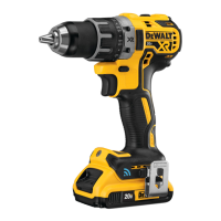
Fuel Gauge Battery Packs (Fig. B)
Some
battery packs include a fuel gauge which
consists of three green LED lights that indicate the level of
charge remaining in the batterypack.
To actuate the fuel gauge, press and hold the fuel gauge button.
A combination of the three green LED lights will illuminate
designating the level of charge left. When the level of charge
in the battery is below the usable limit, the fuel gauge will not
illuminate and the battery will need to berecharged.
NOTE: The fuel gauge is only an indication of the charge left on
the battery pack. It does not indicate tool functionality and is
subject to variation based on product components, temperature
and end-userapplication.