8
a cloth or soft non-metallic brush. Do not use water or
any cleaning solutions.
Important Charging Notes
1. Longest life and best performance can be obtained if
the battery pack is charged when the air temperature is
between 65°F and 75°F (18° – 24°C). DO NOT charge
the battery pack in an air temperature below +40°F
(+4.5°C), or above +104°F (+40°C). This is important
and will prevent serious damage to the battery pack.
2. The charger and battery pack may become warm to the
touch while charging. This is a normal condition, and
does not indicate a problem. To facilitate the cooling of
the battery pack after use, avoid placing the charger or
battery pack in a warm environment such as in a metal
shed or an uninsulated trailer.
3. If the battery pack does not charge properly:
a. Check operation of receptacle by plugging in a lamp
or other appliance;
b. Check to see if receptacle is connected to a light
switch which turns power off when you turn out the
lights;
c. Move the charger and battery pack to a location
where the surrounding air temperature is
approximately 65°F – 75°F (18° – 24°C);
d. If charging problems persist, take the tool, battery
pack and charger to your local service center.
4. The battery pack should be recharged when it fails to
produce sufficient power on jobs which were easily
done previously. DO NOT CONTINUE to use under these
conditions. Follow the charging procedure. You may
also charge a partially used pack whenever you desire
with no adverse effect on the battery pack.
5. Foreign materials of a conductive nature such as, but
not limited to, grinding dust, metal chips, steel wool,
aluminum foil, or any buildup of metallic particles
should be kept away from charger cavities. Always
unplug the charger from the power supply when there
is no battery pack in the cavity. Unplug the charger
before attempting to clean.
6. Do not freeze or immerse the charger in water or any
other liquid.
Storage Recommendations
1. The best storage place is one that is cool and dry, away
from direct sunlight and excess heat or cold.
2. For long storage, it is recommended to store a fully
charged battery pack in a cool dry place out of the
charger for optimal results.
NOTE: Battery packs should not be stored completely
depleted of charge. The battery pack will need to be
recharged before use.
SAVE THESE INSTRUCTIONS FOR
FUTURE USE
COMPONENTS (FIG. A)
WARNING: Never modify the power tool or any part
of it. Damage or personal injury couldresult.
Refer to Figure A at the beginning of this manual for a
complete list ofcomponents.
INTENDED USE
This press tool is designed for professional pressing of
specific plumbing applications only. Only trained personnel
should operate this tool.
DO NOT use under wet conditions or in presence of
flammable liquids orgases.
This press tool is a professional power tool. DO NOT let
children come into contact with the tool. Supervision is
required when inexperienced operators use thistool.
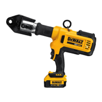
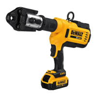
Introduction
The DCE200 Cordless Press Tool uses an electric motor to
power a hydraulic piston pump. The pumping action forces
a ram forward that forces closed a jaw set or attachment.
The attachment mechanically presses fittings onto various
types of tubing to create a tight and permanent seal.
Trigger Switch (Fig. A)
Squeezing the trigger switch
5
advances the hydraulic ram,
while fully releasing the trigger switch stops the advance of
the hydraulic ram.
Reverse Trigger Switch (Fig. A)
Squeezing the reverse trigger switch
6
retracts the
hydraulic ram which releases the pressing action.
Shoulder Strap (Fig. A)
WARNING: The shoulder strap and ring are intended
for transporting the tool. They are not intended for
tethering or securing the tool to a person or object
during use.
WARNING: Do not transport the tool with the
main power ON. Switch the main power OFF prior
totransporting.
Your press tool comes with a shoulder strap. Hook the
shoulder strap clips
14
into the shoulder strap ring
12
.
LED Worklight (Fig. A)
The LED worklight
13
is located on the foot of the tool. The
worklight is activated when the trigger switch is depressed.
It will remain on for 2minutes. After 1 minute, 40 seconds,
the light will dim to 25% indicating that the light is going
to turn off.
LED Display (Fig. C)
The LED display on the top of the press tool includes the
power ON/OFF button
8
maintenance LED
17
, cycle
complete LED
18
, battery state of charge LED
19
, and
temperature LEDs
20
. Refer to the LED Indications chart
for specific information.